Dell PowerEdge C6320 Dell Owners Manual
Dell PowerEdge C6320 Manual
 |
View all Dell PowerEdge C6320 manuals
Add to My Manuals
Save this manual to your list of manuals |
Dell PowerEdge C6320 manual content summary:
- Dell PowerEdge C6320 | Dell Owners Manual - Page 1
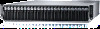
Dell PowerEdge C6320 Owner's Manual Regulatory Model: B08S Regulatory Type: B08S003 - Dell PowerEdge C6320 | Dell Owners Manual - Page 2
potential damage to hardware or loss of data and tells you how to avoid the problem. WARNING: A WARNING indicates a potential for property damage, personal injury, or death. Copyright © 2015 Dell Inc. All rights reserved. This product is protected by U.S. and international copyright and intellectual - Dell PowerEdge C6320 | Dell Owners Manual - Page 3
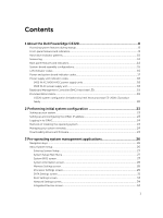
1 About the Dell PowerEdge C6320 8 Accessing system features during startup 8 Front-panel features and indicators...8 Hard-drive indicator patterns...10 Service tag...12 Back panel features and indicators...14 System-board assembly configurations 15 LAN indicator codes...16 Power and system board - Dell PowerEdge C6320 | Dell Owners Manual - Page 4
order...41 Choosing the system boot mode...41 Assigning a system and setup password 42 Deleting or changing an existing system password and setup password 42 4 Installing and removing system components 44 Safety instructions...44 Recommended tools...44 Opening and closing the system ...45 Opening - Dell PowerEdge C6320 | Dell Owners Manual - Page 5
Power supply units...61 Removing a power supply unit...62 Installing a power supply unit...62 System-board card 78 Cable routing for LSI 2008 SAS mezzanine card (1U Node 78 Removing the 1GbE mezzanine card 79 Installing the 1GbE mezzanine card 86 Supported memory module configuration 86 5 - Dell PowerEdge C6320 | Dell Owners Manual - Page 6
service tag using System Setup 92 Cable routing for onboard SATA cables (1U node 93 Power distribution boards...94 Removing a power distribution Board 94 Installing a power distribution board 97 Cable routing for power hard drive system 125 5 Troubleshooting your system 127 Safety first-for - Dell PowerEdge C6320 | Dell Owners Manual - Page 7
I/O device 129 Troubleshooting a NIC ...129 Troubleshooting a wet system...129 Troubleshooting a damaged system 130 Troubleshooting the system battery 130 Troubleshooting power supply units 131 Troubleshooting system cooling problems 131 Troubleshooting a fan...132 Troubleshooting system memory - Dell PowerEdge C6320 | Dell Owners Manual - Page 8
Dell PowerEdge C6320 Accessing system features during startup The following keystrokes provide access to system features during startup. NOTE: Note that the hot-keys of SAS/SATA card or PXE support . Enters the Intel iSCSI setup menu. Front-panel features and indicators Figure - Dell PowerEdge C6320 | Dell Owners Manual - Page 9
four system boards (C6320 RAID card & onboard SATA controller) NOTE: For more information on the direction details of the 2.5 inch hard drive expander configuration support, see the HDD Zoning configuration tool at Dell.com/support. Item 1 Indicator, button or connector Power-on indicator/ system - Dell PowerEdge C6320 | Dell Owners Manual - Page 10
Item Indicator, button or connector Icon 4 System identification indicator/ button for system board 2 6 System identification indicator/ button for system board 4 8 System identification indicator/ button for system board 3 5 Hard drives * Drive cover Hard-drive indicator patterns - Dell PowerEdge C6320 | Dell Owners Manual - Page 11
Figure 4. 2.5 inch hard drive indicators 1. hard-drive status indicator (green and amber) 2. hard-drive activity indicator (green) Controller Onboard Controller PERC 9/LSI 2008 Hard drive type Function SATA2 SAS/SATA2 Drive on-line Fail Slot Empty Drive on-line/ Access Drive Failed Activity - Dell PowerEdge C6320 | Dell Owners Manual - Page 12
Off On 150 ms Off 150 ms Off 500 ms On 500 ms Off 1000 ms Off 6000 ms On 3000 ms Off 000 ms Service tag The Service tag locations for 1U node and the chassis are as follows: Figure - Dell PowerEdge C6320 | Dell Owners Manual - Page 13
chassis The linkage of 12 hard drives for four system boards is presented as below. For other configurations, see Front-panel features and indicators. Figure 8. Service tag linkage NOTE: Hard drives that are under warranty are linked to the appropriate service tag of the node. 13 - Dell PowerEdge C6320 | Dell Owners Manual - Page 14
Back panel features and indicators Figure 9. Back panel with four system boards Item Indicator, button, or connector 1 Power supply unit (PSU2) 2 Power supply unit (PSU1) Icon 3 Single USB port 4 10G NIC 1 port 5 10G NIC 2 port 6 Management port 7 USB to serial port 8 VGA port 9 - Dell PowerEdge C6320 | Dell Owners Manual - Page 15
indicator Description NOTE: When powering on the system, the the system using the power button causes the system to perform a graceful shutdown before power to the system is turned shutdown, press and hold the power button for five seconds. Both a problem. System-board assembly configurations Figure 10. Enumeration - Dell PowerEdge C6320 | Dell Owners Manual - Page 16
amber Solid green Blinking green Condition Linking at 1 Gbps speed Linking at 10 Gbps speed Activity is present: • Pre OS POST • OS without driver • OS with driver Blinking at speed relative to packet density. Off No link/activity present • D0 (uninitialized) • D3 (cold) • S4 (hibernation) 16 - Dell PowerEdge C6320 | Dell Owners Manual - Page 17
Solid green Solid amber Off Blinking green Condition Linking at 1 Gbps speed Linking at 10/100 Mbps speed No access/Idle LAN access/Link up Power and system board indicator codes The LEDs on the system front panel and back panel display status codes during system startup. For location of the - Dell PowerEdge C6320 | Dell Owners Manual - Page 18
1. power supply unit 2. AC power indicator Component AC/DC power indicator Indicator Solid amber Solid green Blinking green Condition Fault (fault of any kind) DC_OK (power good) AC_OK 1600 W AC power supply unit Figure 14. Power supply unit status indicator 1. power supply unit 2. AC power - Dell PowerEdge C6320 | Dell Owners Manual - Page 19
) for BMC debugs. The BMC heart beat LED is green. When the system AC power is connected, the LED lights. When BMC firmware is ready, the BMC heart beat LED blinks. Figure 15. BMC heart beat LED on the C6320 system board 1. BMC heart beat LED Documentation matrix The documentation matrix provides - Dell PowerEdge C6320 | Dell Owners Manual - Page 20
esmmanuals Use Lifecycle Controller Remote Services Dell Lifecycle Controller Remote Services Quick Start Guide at Dell.com/esmmanuals Set up, use, and troubleshoot OpenManage Server Dell OpenManage Server Administrator User's Administrator Guide at Dell.com/openmanagemanuals Install, use, and - Dell PowerEdge C6320 | Dell Owners Manual - Page 21
E5-2660 v3 E5-2650 v3 E5-2623 v3 120W E5-2695 v3 E5-2680 v3 E5-2670 v3 PERC H730 is not supported PERC H730 is not supported 135W (16 cores and 12 cores) E5-2698 v3 E5-2690 v3 135W (8 cores) and 145W E5-2667 v3 E5-2697 v3 PERC - Dell PowerEdge C6320 | Dell Owners Manual - Page 22
bin 3.5 inch hard drive chassis 120W E5-2695 v3 E5-2680 v3 E5-2670 v3 Support maximum 8X HDDs PERC H730/H330 are not supported 2.5 inch hard drive chassis Support maximum 12X HDDs PERC H730/H330 are not supported 135W (16 cores and 12 cores) E5-2698 v3 E5-2690 v3 135W (8 cores) and - Dell PowerEdge C6320 | Dell Owners Manual - Page 23
User's Guide. • Remote Services that includes Web Services Management (WS-Man): For more information, see the Lifecycle Controller Remote Services Quick Start Guide. For more information on setting up and configuring iDRAC, see the Integrated Dell Remote Access Controller User's Guide at Dell.com - Dell PowerEdge C6320 | Dell Owners Manual - Page 24
install the latest BIOS, drivers, and systems management firmware on your system. Ensure that you clear the web browser cache. 1. Go to Dell.com/support/drivers. 2. In the Identify your product section, enter the Service Tag of your system in the Enter a Service Tag or Express Service Code field. 24 - Dell PowerEdge C6320 | Dell Owners Manual - Page 25
Auto-detect your product to allow the system to automatically detect your Service Tag, or select Browse for a product to select your product from the Select a product page. 3. Click Drivers and downloads. The drivers that are applicable to your selection are displayed. 4. Repeat steps 1 through 3 to - Dell PowerEdge C6320 | Dell Owners Manual - Page 26
management applications: • System Setup • Boot Manager • Dell Lifecycle Controller Navigation keys iDRAC Settings/ Device Settings/Service Tag Settings and proceeds with system boot. Displays the System Setup help. About System Setup Using System Setup, you can configure the BIOS settings, iDRAC - Dell PowerEdge C6320 | Dell Owners Manual - Page 27
iDRAC parameters by using the iDRAC Settings utility. For more information about this utility, see the Integrated Dell Remote Access Controller User's Guide at Dell screen click System BIOS on the System Setup Main Menu. The System BIOS screen BIOS version, and Service Tag. Displays information - Dell PowerEdge C6320 | Dell Owners Manual - Page 28
system security settings, such as system password, setup password, TPM security. It also enables or disables support for the power and NMI buttons on the system. Displays version of the Management Engine firmware. System Service Tag Displays the system service tag. System Manufacturer Displays - Dell PowerEdge C6320 | Dell Owners Manual - Page 29
Spare Mode, Spare with Advanced ECC Mode, and Dell Fault Resilient Mode. By default, the Memory Operating Mode Disabled, the system supports NUMA (asymmetric) memory configurations. By default, the Node Interleaving field option Settings screen by clicking System Setup Main Menu > System BIOS - Dell PowerEdge C6320 | Dell Owners Manual - Page 30
Service (ATS) Adjacent Cache Line Prefetch Hardware Prefetcher DCU Streamer Prefetcher DCU IP Prefetcher Execute Disable Logical Processor Idling Configurable TDP X2Apic Mode Number of Cores per Processor Processor 64-bit Support Power (TDP) to lower levels. TDP refers to the maximum amount of power - Dell PowerEdge C6320 | Dell Owners Manual - Page 31
RAID on your system. To view the SATA Settings screen, click System Setup Main Menu > System BIOS > SATA Settings. The SATA Settings screen this field to Auto to enable BIOS support. Set it to OFF to turn off BIOS support. For AHCI or RAID mode, BIOS support is always enabled. Model Drive Type - Dell PowerEdge C6320 | Dell Owners Manual - Page 32
the selected device. For Embedded SATA settings in ATA mode, set this field to Auto to enable BIOS support. Set it to OFF to turn off BIOS support. For AHCI or RAID mode, BIOS support is always enabled. Displays the drive model of the selected device. Displays the type of drive attached to - Dell PowerEdge C6320 | Dell Owners Manual - Page 33
field to Auto to enable BIOS support. Set it to OFF to turn off BIOS support. For AHCI or RAID mode, BIOS support is always enabled. Displays the to specify the boot order. To view the Boot Settings screen, click System Setup Main Menu > System BIOS > Boot Settings. The Boot Settings screen details - Dell PowerEdge C6320 | Dell Owners Manual - Page 34
. You can view the Integrated Devices screen by clicking System Setup Main Menu > System BIOS > Integrated Devices. The Integrated Description Enables or disables the USB 3.0 support. Enable this option only if your operating system supports USB 3.0. If you disable this option, iDRAC features. 34 - Dell PowerEdge C6320 | Dell Owners Manual - Page 35
have no effect on the system. Enables or disables the support for PCIe devices that require large amounts of memory. By is disabled, both the Option ROM and UEFI drivers are disabled. Serial Communication screen You can the Serial Communication screen, click System Setup Main Menu > System BIOS > - Dell PowerEdge C6320 | Dell Owners Manual - Page 36
the serial MUX setting saved in iDRAC. The serial MUX setting can independently be changed in iDRAC. Therefore, loading the BIOS default settings from within the BIOS setup utility may not always revert this is set to Performance Per Watt Optimized (DAPC). DAPC is Dell Active Power Controller. 36 - Dell PowerEdge C6320 | Dell Owners Manual - Page 37
the processor and determines whether to target higher performance or better power savings. Number of Turbo Boot Enabled Cores for Processor 1 NOTE maximum number of cores is enabled. Monitor/Mwait Enables the Monitor/Mwait instructions in the processor. By default, the Monitor/Mwait option is set - Dell PowerEdge C6320 | Dell Owners Manual - Page 38
Intel AES-NI System Password Setup Password Password Status TPM Security TPM Information TPM Status TPM Command Intel TXT Power Button NMI Button Description Improves the speed of applications by performing encryption and decryption using the Advanced Encryption Standard Instruction Set and is set - Dell PowerEdge C6320 | Dell Owners Manual - Page 39
power is restored to the system. By default, the AC Power Recovery option is set to Last. Sets how the system supports staggering of power up after AC power is restored to the system. By default, the AC Power Policy is set to Custom. In the System Setup Main Menu, click System BIOS > System Security - Dell PowerEdge C6320 | Dell Owners Manual - Page 40
the video controller. Selecting Enabled in the operating system does not support UEFI video output standards. This field is only for UEFI boot Boot mode is enabled. System setup options at boot Initiate Setup during POST Load optimal defaults in Setup menu. About Boot Manager - Dell PowerEdge C6320 | Dell Owners Manual - Page 41
Setup access System Setup. Exits the instructions may vary if you have selected BIOS for Boot Mode. 1. From the System Setup system boot mode System Setup enables you to Unified Extensible Firmware Interface (UEFI From the System Setup Main Menu, click support UEFI and can only be installed from the - Dell PowerEdge C6320 | Dell Owners Manual - Page 42
see C6320 system board connectors. You can assign a new System Password and Setup Password or change an existing System Password and Setup to boot the system. 1. To enter System Setup, press F2 immediately after a power-on or reboot. 2. From the System Setup Main Menu, select System BIOS and press - Dell PowerEdge C6320 | Dell Owners Manual - Page 43
If you change the System and Setup password a message prompts you to re-enter the new password. If you delete the System and Setup password, a message prompts you to confirm the deletion. 7. Press Esc to return to the System BIOS screen. Press Esc again, and a message prompts you to - Dell PowerEdge C6320 | Dell Owners Manual - Page 44
only perform troubleshooting and simple repairs as authorized in your product documentation, or as directed by the online or telephone service and support team. Damage due to servicing that is not authorized by Dell is not covered by your warranty. Read and follow the safety instructions that came - Dell PowerEdge C6320 | Dell Owners Manual - Page 45
only perform troubleshooting and simple repairs as authorized in your product documentation, or as directed by the online or telephone service and support team. Damage due to servicing that is not authorized by Dell is not covered by your warranty. Read and follow the safety instructions that came - Dell PowerEdge C6320 | Dell Owners Manual - Page 46
only perform troubleshooting and simple repairs as authorized in your product documentation, or as directed by the online or telephone service and support team. Damage due to servicing that is not authorized by Dell is not covered by your warranty. Read and follow the safety instructions that came - Dell PowerEdge C6320 | Dell Owners Manual - Page 47
troubleshooting and simple repairs as authorized in your product documentation, or as directed by the online or telephone service and support team. Damage due to servicing that is not authorized by Dell is not covered by your warranty. Read and follow the safety instructions cage 4. power connector - Dell PowerEdge C6320 | Dell Owners Manual - Page 48
only perform troubleshooting and simple repairs as authorized in your product documentation, or as directed by the online or telephone service and support team. Damage due to servicing that is not authorized by Dell is not covered by your warranty. Read and follow the safety instructions that came - Dell PowerEdge C6320 | Dell Owners Manual - Page 49
only perform troubleshooting and simple repairs as authorized in your product documentation, or as directed by the online or telephone service and support team. Damage due to servicing that is not authorized by Dell is not covered by your warranty. Read and follow the safety instructions that came - Dell PowerEdge C6320 | Dell Owners Manual - Page 50
only perform troubleshooting and simple repairs as authorized in your product documentation, or as directed by the online or telephone service and support team. Damage due to servicing that is not authorized by Dell is not covered by your warranty. Read and follow the safety instructions that came - Dell PowerEdge C6320 | Dell Owners Manual - Page 51
only perform troubleshooting and simple repairs as authorized in your product documentation, or as directed by the online or telephone service and support team. Damage due to servicing that is not authorized by Dell is not covered by your warranty. Read and follow the safety instructions that came - Dell PowerEdge C6320 | Dell Owners Manual - Page 52
only perform troubleshooting and simple repairs as authorized in your product documentation, or as directed by the online or telephone service and support team. Damage due to servicing that is not authorized by Dell is not covered by your warranty. Read and follow the safety instructions that came - Dell PowerEdge C6320 | Dell Owners Manual - Page 53
only perform troubleshooting and simple repairs as authorized in your product documentation, or as directed by the online or telephone service and support team. Damage due to servicing that is not authorized by Dell is not covered by your warranty. Read and follow the safety instructions that came - Dell PowerEdge C6320 | Dell Owners Manual - Page 54
only perform troubleshooting and simple repairs as authorized in your product documentation, or as directed by the online or telephone service and support team. Damage due to servicing that is not authorized by Dell is not covered by your warranty. Read and follow the safety instructions that came - Dell PowerEdge C6320 | Dell Owners Manual - Page 55
Figure 25. Removing and installing a adapter assembly from the hard-drive carrier 1. adapter assembly 3. hard-drive carrier 2. mach screw (3) 5. Do not install screws in the two screw holes on the side of SSD, which are occupied by the light pipe. Figure 26. Screw holes on the side of SSD and - Dell PowerEdge C6320 | Dell Owners Manual - Page 56
only perform troubleshooting and simple repairs as authorized in your product documentation, or as directed by the online or telephone service and support team. Damage due to servicing that is not authorized by Dell is not covered by your warranty. Read and follow the safety instructions that came - Dell PowerEdge C6320 | Dell Owners Manual - Page 57
only perform troubleshooting and simple repairs as authorized in your product documentation, or as directed by the online or telephone service and support team. Damage due to servicing that is not authorized by Dell is not covered by your warranty. Read and follow the safety instructions that came - Dell PowerEdge C6320 | Dell Owners Manual - Page 58
only perform troubleshooting and simple repairs as authorized in your product documentation, or as directed by the online or telephone service and support team. Damage due to servicing that is not authorized by Dell is not covered by your warranty. Read and follow the safety instructions that came - Dell PowerEdge C6320 | Dell Owners Manual - Page 59
Figure 31. Installing the DC to DC board 1. BBU Bracket 3. DC to DC board 2. Reconnect all the cables. 2. space support (2) Cable routings for SSD and DC to DC board and LSI 2008 Figure 32. Cable routings for SSD and DC to DC Board and LSI - Dell PowerEdge C6320 | Dell Owners Manual - Page 60
only perform troubleshooting and simple repairs as authorized in your product documentation, or as directed by the online or telephone service and support team. Damage due to servicing that is not authorized by Dell is not covered by your warranty. Read and follow the safety instructions that came - Dell PowerEdge C6320 | Dell Owners Manual - Page 61
only perform troubleshooting and simple repairs as authorized in your product documentation, or as directed by the online or telephone service and support team. Damage due to servicing that is not authorized by Dell is not covered by your warranty. Read and follow the safety instructions that came - Dell PowerEdge C6320 | Dell Owners Manual - Page 62
as directed by the online or telephone service and support team. Damage due to servicing that is not authorized by Dell is not covered by your warranty. Read and follow the safety instructions that came with the product. CAUTION: The System requires at least one power supply unit to operate normally - Dell PowerEdge C6320 | Dell Owners Manual - Page 63
only perform troubleshooting and simple repairs as authorized in your product documentation, or as directed by the online or telephone service and support team. Damage due to servicing that is not authorized by Dell is not covered by your warranty. Read and follow the safety instructions that came - Dell PowerEdge C6320 | Dell Owners Manual - Page 64
only perform troubleshooting and simple repairs as authorized in your product documentation, or as directed by the online or telephone service and support team. Damage due to servicing that is not authorized by Dell is not covered by your warranty. Read and follow the safety instructions that came - Dell PowerEdge C6320 | Dell Owners Manual - Page 65
only perform troubleshooting and simple repairs as authorized in your product documentation, or as directed by the online or telephone service and support team. Damage due to servicing that is not authorized by Dell is not covered by your warranty. Read and follow the safety instructions that came - Dell PowerEdge C6320 | Dell Owners Manual - Page 66
only perform troubleshooting and simple repairs as authorized in your product documentation, or as directed by the online or telephone service and support team. Damage due to servicing that is not authorized by Dell is not covered by your warranty. Read and follow the safety instructions that came - Dell PowerEdge C6320 | Dell Owners Manual - Page 67
only perform troubleshooting and simple repairs as authorized in your product documentation, or as directed by the online or telephone service and support team. Damage due to servicing that is not authorized by Dell is not covered by your warranty. Read and follow the safety instructions that came - Dell PowerEdge C6320 | Dell Owners Manual - Page 68
only perform troubleshooting and simple repairs as authorized in your product documentation, or as directed by the online or telephone service and support team. Damage due to servicing that is not authorized by Dell is not covered by your warranty. Read and follow the safety instructions that came - Dell PowerEdge C6320 | Dell Owners Manual - Page 69
only perform troubleshooting and simple repairs as authorized in your product documentation, or as directed by the online or telephone service and support team. Damage due to servicing that is not authorized by Dell is not covered by your warranty. Read and follow the safety instructions that came - Dell PowerEdge C6320 | Dell Owners Manual - Page 70
only perform troubleshooting and simple repairs as authorized in your product documentation, or as directed by the online or telephone service and support team. Damage due to servicing that is not authorized by Dell is not covered by your warranty. Read and follow the safety instructions that came - Dell PowerEdge C6320 | Dell Owners Manual - Page 71
only perform troubleshooting and simple repairs as authorized in your product documentation, or as directed by the online or telephone service and support team. Damage due to servicing that is not authorized by Dell is not covered by your warranty. Read and follow the safety instructions that came - Dell PowerEdge C6320 | Dell Owners Manual - Page 72
only perform troubleshooting and simple repairs as authorized in your product documentation, or as directed by the online or telephone service and support team. Damage due to servicing that is not authorized by Dell is not covered by your warranty. Read and follow the safety instructions that came - Dell PowerEdge C6320 | Dell Owners Manual - Page 73
only perform troubleshooting and simple repairs as authorized in your product documentation, or as directed by the online or telephone service and support team. Damage due to servicing that is not authorized by Dell is not covered by your warranty. Read and follow the safety instructions that came - Dell PowerEdge C6320 | Dell Owners Manual - Page 74
only perform troubleshooting and simple repairs as authorized in your product documentation, or as directed by the online or telephone service and support team. Damage due to servicing that is not authorized by Dell is not covered by your warranty. Read and follow the safety instructions that came - Dell PowerEdge C6320 | Dell Owners Manual - Page 75
only perform troubleshooting and simple repairs as authorized in your product documentation, or as directed by the online or telephone service and support team. Damage due to servicing that is not authorized by Dell is not covered by your warranty. Read and follow the safety instructions that came - Dell PowerEdge C6320 | Dell Owners Manual - Page 76
only perform troubleshooting and simple repairs as authorized in your product documentation, or as directed by the online or telephone service and support team. Damage due to servicing that is not authorized by Dell is not covered by your warranty. Read and follow the safety instructions that came - Dell PowerEdge C6320 | Dell Owners Manual - Page 77
only perform troubleshooting and simple repairs as authorized in your product documentation, or as directed by the online or telephone service and support team. Damage due to servicing that is not authorized by Dell is not covered by your warranty. Read and follow the safety instructions that came - Dell PowerEdge C6320 | Dell Owners Manual - Page 78
troubleshooting and simple repairs as authorized in your product documentation, or as directed by the online or telephone service and support team. Damage due to servicing that is not authorized by Dell is not covered by your warranty. Read and follow the safety instructions card (1U node) Item - Dell PowerEdge C6320 | Dell Owners Manual - Page 79
only perform troubleshooting and simple repairs as authorized in your product documentation, or as directed by the online or telephone service and support team. Damage due to servicing that is not authorized by Dell is not covered by your warranty. Read and follow the safety instructions that came - Dell PowerEdge C6320 | Dell Owners Manual - Page 80
Figure 49. Removing and installing the expansion-card bracket 1. screw (3) 3. system-board assembly 2. expansion-card bracket 5. Remove the screws that secure the 1GbE mezzanine card assembly. 6. Lift the 1GbE mezzanine card assembly away from the card bridge board on the system board. Figure 50 - Dell PowerEdge C6320 | Dell Owners Manual - Page 81
only perform troubleshooting and simple repairs as authorized in your product documentation, or as directed by the online or telephone service and support team. Damage due to servicing that is not authorized by Dell is not covered by your warranty. Read and follow the safety instructions that came - Dell PowerEdge C6320 | Dell Owners Manual - Page 82
only perform troubleshooting and simple repairs as authorized in your product documentation, or as directed by the online or telephone service and support team. Damage due to servicing that is not authorized by Dell is not covered by your warranty. Read and follow the safety instructions that came - Dell PowerEdge C6320 | Dell Owners Manual - Page 83
Figure 53. Removing and installing the 10GbE mezzanine card assembly 1. screw (4) 2. 10GbE mezzanine card assembly 7. Remove the two screws that secure the 10GbE mezzanine card to the bracket. 8. Remove the 10GbE mezzanine card from the bracket. Figure 54. Removing and installing the 10GbE - Dell PowerEdge C6320 | Dell Owners Manual - Page 84
only perform troubleshooting and simple repairs as authorized in your product documentation, or as directed by the online or telephone service and support team. Damage due to servicing that is not authorized by Dell is not covered by your warranty. Read and follow the safety instructions that came - Dell PowerEdge C6320 | Dell Owners Manual - Page 85
only perform troubleshooting and simple repairs as authorized in your product documentation, or as directed by the online or telephone service and support team. Damage due to servicing that is not authorized by Dell is not covered by your warranty. Read and follow the safety instructions that came - Dell PowerEdge C6320 | Dell Owners Manual - Page 86
2. For the location of the memory modules, see C6320 system board connectors. Memory slot features • Support 8 channels, 16 RDIMMs of DDR4 • Speed up to 2133MT/s • Max. capacities: 256GB with 16GB RDIMM 256GB with 32GB RDIMM • Support DDR4 • Support ECC NOTE: Linux operating system does not - Dell PowerEdge C6320 | Dell Owners Manual - Page 87
only perform troubleshooting and simple repairs as authorized in your product documentation, or as directed by the online or telephone service and support team. Damage due to servicing that is not authorized by Dell is not covered by your warranty. Read and follow the safety instructions that came - Dell PowerEdge C6320 | Dell Owners Manual - Page 88
only perform troubleshooting and simple repairs as authorized in your product documentation, or as directed by the online or telephone service and support team. Damage due to servicing that is not authorized by Dell is not covered by your warranty. Read and follow the safety instructions that came - Dell PowerEdge C6320 | Dell Owners Manual - Page 89
enter System Setup, and troubleshooting and simple repairs as authorized in your product documentation, or as directed by the online or telephone service and support team. Damage due to servicing that is not authorized by Dell is not covered by your warranty. Read and follow the safety instructions - Dell PowerEdge C6320 | Dell Owners Manual - Page 90
firmly support the connector Setup program to confirm that the battery is operating properly. See Entering System Setup. 9. Enter the correct time and date in the System Setup program's and Time and Date fields. 10. Exit the System Setup - Dell PowerEdge C6320 | Dell Owners Manual - Page 91
troubleshooting and simple repairs as authorized in your product documentation, or as directed by the online or telephone service and support team. Damage due to servicing that is not authorized by Dell is not covered by your warranty. Read and follow the safety instructions node 2. system board 91 - Dell PowerEdge C6320 | Dell Owners Manual - Page 92
only perform troubleshooting and simple repairs as authorized in your product documentation, or as directed by the online or telephone service and support team. Damage due to servicing that is not authorized by Dell is not covered by your warranty. Read and follow the safety instructions that came - Dell PowerEdge C6320 | Dell Owners Manual - Page 93
connect the other end of the cable to the corresponding connectors on the system board. Figure 61. Cable routing for onboard SATA cables (1U node) Item Cable Onboard SATA cable From (system board) To (system board) Onboard SATA output SAS/SATA input connector 0 connector 0 Onboard SATA cable - Dell PowerEdge C6320 | Dell Owners Manual - Page 94
only perform troubleshooting and simple repairs as authorized in your product documentation, or as directed by the online or telephone service and support team. Damage due to servicing that is not authorized by Dell is not covered by your warranty. Read and follow the safety instructions that came - Dell PowerEdge C6320 | Dell Owners Manual - Page 95
Remove the screws securing the power distribution board 1 to the system. 9. Lift the power distribution board 1 out of the system. Figure 65. Removing and installing the power distribution board 1 1. power distribution board 1 2. screw (8) 10. Lift the power distribution board connector from the - Dell PowerEdge C6320 | Dell Owners Manual - Page 96
securing the power distribution board 2 to the system. 15. Lift the power distribution board 2 out of the system. Figure 67. Removing and installing a power distribution board 2 1. screw (4) 2. power distribution board 2 Related Information Opening the system Removing a power supply unit 96 - Dell PowerEdge C6320 | Dell Owners Manual - Page 97
only perform troubleshooting and simple repairs as authorized in your product documentation, or as directed by the online or telephone service and support team. Damage due to servicing that is not authorized by Dell is not covered by your warranty. Read and follow the safety instructions that came - Dell PowerEdge C6320 | Dell Owners Manual - Page 98
Cable Hard-drive backplane power cable From (power distribution boards) Hard-drive backplane power connector (J84) To Backplane Hard-drive backplane power cable Hard-drive backplane Backplane power connector (J29) Power distribution board Control connector (J31) Power distribution board cable - Dell PowerEdge C6320 | Dell Owners Manual - Page 99
only perform troubleshooting and simple repairs as authorized in your product documentation, or as directed by the online or telephone service and support team. Damage due to servicing that is not authorized by Dell is not covered by your warranty. Read and follow the safety instructions that came - Dell PowerEdge C6320 | Dell Owners Manual - Page 100
. You must route these cables properly when you replace them to prevent the cables from being pinched or crimped. 8. Remove the screw that secures the power cable cover to the upper middle plane. 9. Lift it up straight from the locking hole on the upper middle plane. Then, lift it completely out - Dell PowerEdge C6320 | Dell Owners Manual - Page 101
Figure 72. Removing and installing the power cables 1. power cables (4) 2. screw (4) 11. Remove the screws that secure the upper middle plane to the 1. screw (8) 2. upper middle plane 13. Remove the screws that secure the mid-plane holder support to the chassis. 14. Lift the mid-plane holder - Dell PowerEdge C6320 | Dell Owners Manual - Page 102
Figure 74. Removing and installing the mid-plane holder support 1. screw (3) 2. mid-plane holder support 15. Remove the screws that secure the mid-plane holder to the the cables from being pinched or crimped. 18. Remove the power cable cover from the lower middle plane. 19. Remove the four - Dell PowerEdge C6320 | Dell Owners Manual - Page 103
only perform troubleshooting and simple repairs as authorized in your product documentation, or as directed by the online or telephone service and support team. Damage due to servicing that is not authorized by Dell is not covered by your warranty. Read and follow the safety instructions that came - Dell PowerEdge C6320 | Dell Owners Manual - Page 104
these cables properly on the chassis to prevent them from being pinched or crimped. 13. Secure the screws that secure the power cables to the upper middle plane. 14. Replace the power cable cover to the upper lower middle plane. 15. Place the middle-wall bracket into the chassis. 16. Replace the - Dell PowerEdge C6320 | Dell Owners Manual - Page 105
Item Cable Hard-drive backplane cable From (top Middle Plane) To (direct backplane) (hard drive 1, 2, 3 and 4) for system board 1 (from (J1) top to bottom) mini-SAS connector for system board 3 and 4 (hard drive 1, 2, 3 and 4) (J3) SATA2 hard drive connectors 1, 2 and 3 for system board 3 ( - Dell PowerEdge C6320 | Dell Owners Manual - Page 106
Figure 79. Cable routing−top middle plane to direct backplane for 24 x2.5 inch hard-drive configuration Item Cable Hard-drive backplane cable From (top middle plane) To (direct backplane) Mini-SAS connector for system board 1 and 2 (hard drive 1, 2, 3 and 4) (J1) SATA2 hard drive connectors 1 - Dell PowerEdge C6320 | Dell Owners Manual - Page 107
Figure 80. Cable routing−bottom middle plane to direct backplane for 24 x2.5 inch hard-drive configuration Item Cable Hard-drive backplane cable From (bottom middle plane) Mini-SAS connector for system board 1 and 2 (hard drive 1, 2, 3 and 4) (J1) To (direct backplane) SATA2 hard drive - Dell PowerEdge C6320 | Dell Owners Manual - Page 108
Cable routing for middle plane to 2.5 inch hard-drive backplane for expander configuration Figure 81. Cable routing−top middle plane to 2.5 inch hard drive for expander configuration Item Cable Hard-drive backplane cable From (top middle plane) To (expander card) Mini-SAS connector for Mini-SAS - Dell PowerEdge C6320 | Dell Owners Manual - Page 109
only perform troubleshooting and simple repairs as authorized in your product documentation, or as directed by the online or telephone service and support team. Damage due to servicing that is not authorized by Dell is not covered by your warranty. Read and follow the safety instructions that came - Dell PowerEdge C6320 | Dell Owners Manual - Page 110
to prevent the cables from being pinched or crimped. Figure 83. Back view of the 3.5 inch direct backplane 1. backplane power connector for power supply unit 1 3. SGPIO connector 4 for system board 4 5. SGPIO connector 2 for system board 2 7. backplane jumper 9. SATA2 hard drive connectors 1, 2 and - Dell PowerEdge C6320 | Dell Owners Manual - Page 111
1 9. SGPIO connector A for system board 2 11. SGPIO connector A for system board 3 13. SGPIO connector A for system board 4 15. backplane power connector for power supply unit 2 6. SATA2 hard drive connectors 1 to 6 for system board 1 (from right to left) 8. SGPIO connector B for system board 1 10 - Dell PowerEdge C6320 | Dell Owners Manual - Page 112
Figure 86. Removing and installing the hard-drive cage cable routing for middle plane to direct backplane 1. hard drive cage 3. screw (2) 2. front-panel assembly (2) 9. Remove the screws that secure the backplane to the hard-drive cage. 10. Remove the backplane from the hard-drive cage. Figure - Dell PowerEdge C6320 | Dell Owners Manual - Page 113
troubleshooting and simple repairs as authorized in your product documentation, or as directed by the online or telephone service and support team. Damage due to servicing that is not authorized by Dell is not covered by your warranty. Read and follow the safety instructions the power distribution - Dell PowerEdge C6320 | Dell Owners Manual - Page 114
hard-drive backplane for expander configuration 1. backplane power connector for power supply 1 3. Expander-card connector 2 2. Expander-card connector 1 4. backplane power connector for power supply 2 Figure 89. Top view of the expander card 1. Power control connector 3. mini-SAS connector (12 - Dell PowerEdge C6320 | Dell Owners Manual - Page 115
Figure 90. Removing and installing the 2.5" hard-drive backplane for expander configuration 1. hard drive cage 2. screw (2) 7. Remove the screws that secure the front-panel assemblies to the chassis. 8. Remove the hard-drive cage from the chassis. Figure 91. Removing and installing the 2.5 inch - Dell PowerEdge C6320 | Dell Owners Manual - Page 116
Figure 92. Removing and installing the screws securing the expander card assembly to the hard-drive cage 1. hard drive cage 2. screw (6) 10. Remove the expander card assembly from the hard-drive cage. Figure 93. Removing and installing the 2.5 inch hard-drive expander card assembly from the hard - Dell PowerEdge C6320 | Dell Owners Manual - Page 117
troubleshooting and simple repairs as authorized in your product documentation, or as directed by the online or telephone service and support team. Damage due to servicing that is not authorized by Dell is not covered by your warranty. Read and follow the safety instructions the power distribution - Dell PowerEdge C6320 | Dell Owners Manual - Page 118
troubleshooting and simple repairs as authorized in your product documentation, or as directed by the online or telephone service and support team. Damage due to servicing that is not authorized by Dell is not covered by your warranty. Read and follow the safety instructions the power distribution - Dell PowerEdge C6320 | Dell Owners Manual - Page 119
Figure 95. Removing and installing a front panel assembly 1. front-panel assembly 2. screw (2) 11. Push aside the retention hooks on the front-panel assembly. 12. Remove the front panel from the front-panel assembly. Figure 96. Removing and installing a front panel 1. front-panel assembly 3. - Dell PowerEdge C6320 | Dell Owners Manual - Page 120
troubleshooting and simple repairs as authorized in your product documentation, or as directed by the online or telephone service and support team. Damage due to servicing that is not authorized by Dell is not covered by your warranty. Read and follow the safety instructions the power distribution - Dell PowerEdge C6320 | Dell Owners Manual - Page 121
the power distribution troubleshooting and simple repairs as authorized in your product documentation, or as directed by the online or telephone service and support team. Damage due to servicing that is not authorized by Dell is not covered by your warranty. Read and follow the safety instructions - Dell PowerEdge C6320 | Dell Owners Manual - Page 122
of the cable to the connectors on the sensor board and the front panel 2 respectively. 2. Connect the front panel cable to the connector on the power distribution board 1, and connect the other end of the cable to the connector on the front panel 1. Figure 98. Cable routing−sensor board and front - Dell PowerEdge C6320 | Dell Owners Manual - Page 123
troubleshooting and simple repairs as authorized in your product documentation, or as directed by the online or telephone service and support team. Damage due to servicing that is not authorized by Dell is not covered by your warranty. Read and follow the safety instructions the power distribution - Dell PowerEdge C6320 | Dell Owners Manual - Page 124
Figure 99. Removing and installing the sensor board assembly 1. sensor board assembly 2. screw (2) 10. Remove the screw that secures the sensor board to the sensor-board holder. 11. Remove the sensor board from the sensor-board holder. Figure 100. Removing and installing the sensor board 1. - Dell PowerEdge C6320 | Dell Owners Manual - Page 125
troubleshooting and simple repairs as authorized in your product documentation, or as directed by the online or telephone service and support team. Damage due to servicing that is not authorized by Dell is not covered by your warranty. Read and follow the safety instructions the power distribution - Dell PowerEdge C6320 | Dell Owners Manual - Page 126
Figure 101. Cable routing−sensor board and front panel Item Cable From (power To (sensor board and front panels) distribution board) Sensor board Sensor board power Sensor board cable connector (J1) Front panel cable Front panel connector (J16) Front panel 2 Front panel cable Front - Dell PowerEdge C6320 | Dell Owners Manual - Page 127
and support team. Damage due to servicing that is not authorized by Dell is not covered by your warranty. Read and follow the safety instructions that came with the product. Minimum configuration to POST • One power supply unit • One Processor (CPU) in socket CPU1 (minimum for troubleshooting) • One - Dell PowerEdge C6320 | Dell Owners Manual - Page 128
. If the problem is not resolved, proceed to the next step to begin troubleshooting the other USB devices attached to the system. 5. Power down all attached USB devices and disconnect them from the system. 6. Restart the system and, if your keyboard is functioning, enter the system setup program - Dell PowerEdge C6320 | Dell Owners Manual - Page 129
only perform troubleshooting and simple repairs as authorized in your product documentation, or as directed by the online or telephone service and support team. Damage due to servicing that is not authorized by Dell is not covered by your warranty. Read and follow the safety instructions that came - Dell PowerEdge C6320 | Dell Owners Manual - Page 130
only perform troubleshooting and simple repairs as authorized in your product documentation, or as directed by the online or telephone service and support team. Damage due to servicing that is not authorized by Dell is not covered by your warranty. Read and follow the safety instructions that came - Dell PowerEdge C6320 | Dell Owners Manual - Page 131
service and support team. Damage due to servicing that is not authorized by Dell is not covered by your warranty. Read and follow the safety instructions that came with the product. Ensure that none of the following conditions exist: • System cover, cooling shroud, drive blank, power supply - Dell PowerEdge C6320 | Dell Owners Manual - Page 132
only perform troubleshooting and simple repairs as authorized in your product documentation, or as directed by the online or telephone service and support team. Damage due to servicing that is not authorized by Dell is not covered by your warranty. Read and follow the safety instructions that came - Dell PowerEdge C6320 | Dell Owners Manual - Page 133
only perform troubleshooting and simple repairs as authorized in your product documentation, or as directed by the online or telephone service and support team. Damage due to servicing that is not authorized by Dell is not covered by your warranty. Read and follow the safety instructions that came - Dell PowerEdge C6320 | Dell Owners Manual - Page 134
only perform troubleshooting and simple repairs as authorized in your product documentation, or as directed by the online or telephone service and support team. Damage due to servicing that is not authorized by Dell is not covered by your warranty. Read and follow the safety instructions that came - Dell PowerEdge C6320 | Dell Owners Manual - Page 135
the system-board assembly. 13. Replace processor 1 with processor 2. 14. Repeat step 9 through step 11. If you have tested both the processors and the problem persists, the system board is faulty. See Getting help. IRQ assignment conflicts Most PCI devices can share an IRQ with another device, but - Dell PowerEdge C6320 | Dell Owners Manual - Page 136
IRQ Line IRQ13 IRQ14 IRQ15 Assignment Processor Primary IDE controller Secondary IDE controller NOTE: PCI_IRQ_POOL_DEFINITION means BIOS code assign in runtime. 136 - Dell PowerEdge C6320 | Dell Owners Manual - Page 137
102. C6320 system board connectors 1. rear USB Connector 1 3. mini-SAS Connector 0-3 5. onboard SATA Connector 4 7. mini-SAS Connector 6-9 9. DIMM sockets for processor 1 11. DIMM sockets for processor 2 13. SAS/SATA connector 4 15. middle plane connector 17. control panel connector 19. high power - Dell PowerEdge C6320 | Dell Owners Manual - Page 138
hard drive connectors 1, 2 and 3 for system board 3 (from top to bottom) Figure 104. Back view of the backplane 1. backplane power connector for power supply 2. 1x8pin fan controller board connector unit 1 3. SGPIO connector 4 for system board 4 4. SGPIO connector 3 for system board 3 5. SGPIO - Dell PowerEdge C6320 | Dell Owners Manual - Page 139
to right) hard drive connectors 1 to 6 for system board 4 (from left to right) Figure 106. Back view of the backplane 1. backplane power connector for power supply 1 2. system fan board connector 3. SATA2 and SAS connectors 1 to 6 for system 4. SATA2 and SAS connectors 1 to 6 for system board - Dell PowerEdge C6320 | Dell Owners Manual - Page 140
backplane for expander configuration Figure 108. Back view of the backplane 1. backplane power connector for power supply 1 2. 3. expander-card connector 2 4. expander-card connector 1 backplane power connector for power supply 2 Figure 109. Top view of the 2.5 inch hard-drive expander card - Dell PowerEdge C6320 | Dell Owners Manual - Page 141
Middle plane connectors Figure 110. Middle plane connectors 1. 2x17pin control connector for power 2. distribution board 1 3. mini-SAS connector for system board 3 and 4 4. (hard drive 1, 2, 3 and 4) 5. mini-SAS connector for system board 1 and 2 (hard drive 1, 2, 3 and 4) mini-SAS connector - Dell PowerEdge C6320 | Dell Owners Manual - Page 142
3. mini-SAS connector (port 4-7) Powerville dual port 1GbE 4. mini-SAS connector (port 0-3) Figure 112. Powerville dual port 1GbE connectors 1. Powerville dual port 1GbE card 3. NIC 1 connector 2. mezzanine card connector 4. NIC 2 connector 142 - Dell PowerEdge C6320 | Dell Owners Manual - Page 143
dual port 10GbE connectors 1. Twinville dual port 10GbE card 3. NIC 1 connector 2. mezzanine card connector 4. NIC 2 connector Power distribution board 1 connectors Figure 114. Power distribution board 1 connectors 1. front panel connector for system board 1 and 2 2. 3. hard drive backplane - Dell PowerEdge C6320 | Dell Owners Manual - Page 144
8. 1x8pin control connector to hard drive and 3 backplane 9. front panel connector for system board 3 and 4 Power distribution board 2 connectors Figure 115. Power distribution board 2 connectors 1. bridge card connector Sensor board connectors 2. 1x10pin control connector Figure 116. Sensor - Dell PowerEdge C6320 | Dell Owners Manual - Page 145
only perform troubleshooting and simple repairs as authorized in your product documentation, or as directed by the online or telephone service and support team. Damage due to servicing that is not authorized by Dell is not covered by your warranty. Read and follow the safety instructions that came - Dell PowerEdge C6320 | Dell Owners Manual - Page 146
Figure 118. Direct backplane jumper settings Table 6. Jumpers installed on direct backplane Jumper SW1 (pin1-2) Function Reserved SW2 (pin3-4) Reserved SW3 (pin5-6) SGPIO I2C Select SW4 (pin7-8) MFG Test Off *Disable *Disable *Disable *Disable On Enable Enable Enable Enable NOTE: The * - Dell PowerEdge C6320 | Dell Owners Manual - Page 147
services may not be available in your area. To contact Dell for sales, technical support, or customer-service issues: 1. Go to Dell.com/support. be done by visiting Dell.com/QRL or by using your smartphone and a model specific Quick Resource (QR) code located on your Dell PowerEdge system. To try - Dell PowerEdge C6320 | Dell Owners Manual - Page 148
148
-
 1
1 -
 2
2 -
 3
3 -
 4
4 -
 5
5 -
 6
6 -
 7
7 -
8
-
9
-
10
-
11
-
12
-
13
-
14
-
15
-
16
-
17
-
18
-
19
-
20
-
21
-
22
-
23
-
24
-
25
-
26
-
27
-
28
-
29
-
30
-
31
-
32
-
33
-
34
-
35
-
36
-
37
-
38
-
39
-
40
-
41
-
42
-
43
-
44
-
45
-
46
-
47
-
48
-
49
-
50
-
51
-
52
-
53
-
54
-
55
-
56
-
57
-
58
-
59
-
60
-
61
-
62
-
63
-
64
-
65
-
66
-
67
-
68
-
69
-
70
-
71
-
72
-
73
-
74
-
75
-
76
-
77
-
78
-
79
-
80
-
81
-
82
-
83
-
84
-
85
-
86
-
87
-
88
-
89
-
90
-
91
-
92
-
93
-
94
-
95
-
96
-
97
-
98
-
99
-
100
-
101
-
102
-
103
-
104
-
105
-
106
-
107
-
108
-
109
-
110
-
111
-
112
-
113
-
114
-
115
-
116
-
117
-
118
-
119
-
120
-
121
-
122
-
123
-
124
-
125
-
126
-
127
-
128
-
129
-
130
-
131
-
132
-
133
-
134
-
135
-
136
-
137
-
138
-
139
-
140
-
141
-
142
-
143
-
144
-
145
-
146
-
147
-
148
 |
 |

Dell PowerEdge C6320
Owner's Manual
Regulatory Model: B08S
Regulatory Type: B08S003