Dell PowerEdge C6320 Dell Owners Manual - Page 122
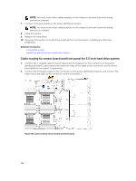
Cable routing for sensor board and front panel for 3.5 inch hard drive system
 |
View all Dell PowerEdge C6320 manuals
Add to My Manuals
Save this manual to your list of manuals |
Page 122 highlights
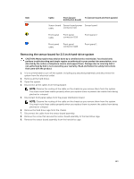
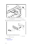
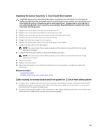
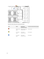
NOTE: You must route these cables properly on the chassis to prevent them from being pinched or crimped. 7. Connect front panel cables to the power distribution board. NOTE: You must route these cables properly on the chassis to prevent them from being pinched or crimped. 8. Close the system. 9. Replace the hard drives. 10. Reconnect the system to its electrical outlet and turn on the system, including any attached peripherals. Related Information Closing the system Installing a hard drive into a hard-drive carrier Cable routing for sensor board and front panel for 3.5 inch hard drive system 1. Connect the Y-shaped cable for sensor board and front panel 2 to the connector on the power distribution board 1, and connect the other two ends of the cable to the connectors on the sensor board and the front panel 2 respectively. 2. Connect the front panel cable to the connector on the power distribution board 1, and connect the other end of the cable to the connector on the front panel 1. Figure 98. Cable routing−sensor board and front panel 122
-
 1
1 -
2
-
3
-
4
-
5
-
6
-
7
-
8
-
9
-
10
-
11
-
12
-
13
-
14
-
15
-
16
-
17
-
18
-
19
-
20
-
21
-
22
-
23
-
24
-
25
-
26
-
27
-
28
-
29
-
30
-
31
-
32
-
33
-
34
-
35
-
36
-
37
-
38
-
39
-
40
-
41
-
42
-
43
-
44
-
45
-
46
-
47
-
48
-
49
-
50
-
51
-
52
-
53
-
54
-
55
-
56
-
57
-
58
-
59
-
60
-
61
-
62
-
63
-
64
-
65
-
66
-
67
-
68
-
69
-
70
-
71
-
72
-
73
-
74
-
75
-
76
-
77
-
78
-
79
-
80
-
81
-
82
-
83
-
84
-
85
-
86
-
87
-
88
-
89
-
90
-
91
-
92
-
93
-
94
-
95
-
96
-
97
-
98
-
99
-
100
-
101
-
102
-
103
-
104
-
105
-
106
-
107
-
108
-
109
-
110
-
111
-
112
-
113
-
114
-
115
-
116
-
 117
117 -
 118
118 -
 119
119 -
 120
120 -
 121
121 -
 122
122 -
 123
123 -
 124
124 -
 125
125 -
 126
126 -
 127
127 -
128
-
129
-
130
-
131
-
132
-
133
-
134
-
135
-
136
-
137
-
138
-
139
-
140
-
141
-
142
-
143
-
144
-
145
-
146
-
147
-
148
 |
 |
