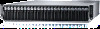
Dell PowerEdge C6320 Dell Owners Manual - Page 61
Installing the SATA DOM, Cable routing for SATA DOM and LSI 2008, Power supply units
 |
View all Dell PowerEdge C6320 manuals
Add to My Manuals
Save this manual to your list of manuals |
Page 61 highlights
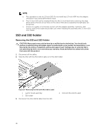
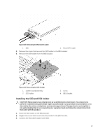
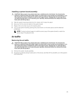
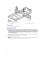
Installing the SATA DOM CAUTION: Many repairs may only be done by a certified service technician. You should only perform troubleshooting and simple repairs as authorized in your product documentation, or as directed by the online or telephone service and support team. Damage due to servicing that is not authorized by Dell is not covered by your warranty. Read and follow the safety instructions that came with the product. 1. Holding the SATA DOM by its edges, position it so that the card edge connector aligns with the onboard SATA connector 5 on the system board. 2. Press the SATA DOM with your thumbs until it is fully seated. 3. Reconnect all the cables. Cable routing for SATA DOM and LSI 2008 Figure 34. Cable Routing for SATA DOM and LSI 2008 Item Cable Mini-SAS cable From (LSI 2008 SAS Mezzanine Card) Mini-SAS connector 4~7 (J4) On LSI 2008 SAS Mezzanine Card To (System Board) SAS/SATA connectors 4&5 Mini-SAS connector 0~3 (J3) On LSI 2008 SAS Mezzanine Card Mini-SAS HD Connector 0-3 SATA DOM power cable SATA DOM HDD Power Connector on the system board Power supply units NOTE: The following table lists the maximum supported configuration where power supply unit redundancy is guaranteed. NOTE: Configurations higher than indicated in the table may change the power supply unit mode to non-redundant. In non-redundant mode if the power requirement exceeds the installed system power capacity, the BIOS will throttle the processors. Also, if Processor Power Capping is enabled, then processor throttling occurs on configurations that exceed the cap value. NOTE: Both the power supply units are swappable, and they can support hot swap in any condition if the system has power throttling feature. 61
-
 1
1 -
2
-
3
-
4
-
5
-
6
-
7
-
8
-
9
-
10
-
11
-
12
-
13
-
14
-
15
-
16
-
17
-
18
-
19
-
20
-
21
-
22
-
23
-
24
-
25
-
26
-
27
-
28
-
29
-
30
-
31
-
32
-
33
-
34
-
35
-
36
-
37
-
38
-
39
-
40
-
41
-
42
-
43
-
44
-
45
-
46
-
47
-
48
-
49
-
50
-
51
-
52
-
53
-
54
-
55
-
 56
56 -
 57
57 -
 58
58 -
 59
59 -
 60
60 -
 61
61 -
 62
62 -
 63
63 -
 64
64 -
 65
65 -
 66
66 -
67
-
68
-
69
-
70
-
71
-
72
-
73
-
74
-
75
-
76
-
77
-
78
-
79
-
80
-
81
-
82
-
83
-
84
-
85
-
86
-
87
-
88
-
89
-
90
-
91
-
92
-
93
-
94
-
95
-
96
-
97
-
98
-
99
-
100
-
101
-
102
-
103
-
104
-
105
-
106
-
107
-
108
-
109
-
110
-
111
-
112
-
113
-
114
-
115
-
116
-
117
-
118
-
119
-
120
-
121
-
122
-
123
-
124
-
125
-
126
-
127
-
128
-
129
-
130
-
131
-
132
-
133
-
134
-
135
-
136
-
137
-
138
-
139
-
140
-
141
-
142
-
143
-
144
-
145
-
146
-
147
-
148
 |
 |
