Dell PowerEdge M520 Dell M8428-k Getting Started Guide - Page 12
Connecting the converged network switch to the fabric, M8428-k Hardware Reference Manual
 |
View all Dell PowerEdge M520 manuals
Add to My Manuals
Save this manual to your list of manuals |
Page 12 highlights
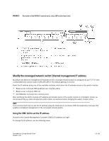
Connecting the converged network switch to the fabric 1. The switch module is delivered with FC 8G SFP transceivers installed in the four fibre channel ports. 2. If you need to connect the Ethernet ports, install 10GE SFP+ transceivers or twin-ax cables in the external ports as required. Be sure you have all the necessary SFP transceivers as well as either optical or active twin-ax copper cables. a. If necessary, remove the end caps from the SFP. b. Orient the transceiver correctly and insert it into a port until it is firmly seated and the latching mechanism clicks. For instructions specific to the type of transceiver, refer to the transceiver manufacturer's documentation. c. Repeat substeps a, b, and c for the remaining ports, as required. NOTE Use only Dell-approved SFPs or active twin-ax copper cables in the appropriate external optical ports of this module. The FC 8G SFP transceivers included in the 4 Fibre Channel ports (25, 26, 27, and 0) of the switch module are not compatible with the Ethernet ports (17 through 24). The Ethernet ports should be populated with Dell-Approved 10GE SFP+ transceivers, or active twin-ax copper cables (not included). ATTENTION A cable should not be bent to a radius less than 5.08 cm (2 inches) under full tensile load and 3.048 cm (1.2 inches) with no tensile load. Tie wraps are not recommended for optical cables because they are easily over tightened. d. Orient a cable connector so that the key (the ridge on one side of connector) aligns with the slot in the transceiver e. Insert the cable into the transceiver until the latching mechanism clicks. For instructions specific to cable type, refer to the cable manufacturer's documentation. f. Repeat for the remaining transceivers as required. 3. Connect the cables to the transceivers. The transceivers are keyed to ensure correct orientation. If a transceiver does not install easily, ensure that it is correctly oriented and that the end caps have been removed. 4. Check the LEDs to verify that all components are functional. For information about LED patterns, see the "Operating the converged network switch" chapter in the Dell M8428-k Hardware Reference Manual. NOTE Commands below are run from the FOS CLI, as needed exit the CEE CLI, or login to the Switch with a terminal emulator session and gain access the FOS prompt M8428-k:Admin> 5. Once the switch module FC port is connected to an FC SAN switch, the ports need to be enabled. From the switch module FOS CLI enter the following command for the ports being used (this can also be enabled from the switch GUI): M8428-k:admin> portcfgpersistentenable , where the port# is 25, 26, 27 or 0. 6. Verify the correct operation of the converged network switch by typing the switchShow command from the workstation. This command provides information about the switch module and port status. 12 of 192 Dell M8428-k Getting Started Guide MHWKY A01
-
 1
1 -
2
-
3
-
4
-
5
-
6
-
 7
7 -
 8
8 -
 9
9 -
 10
10 -
 11
11 -
 12
12 -
 13
13 -
 14
14 -
 15
15 -
 16
16 -
 17
17 -
18
-
19
-
20
-
21
-
22
-
23
-
24
-
25
-
26
-
27
-
28
-
29
-
30
-
31
-
32
-
33
-
34
-
35
-
36
-
37
-
38
-
39
-
40
-
41
-
42
-
43
-
44
-
45
-
46
-
47
-
48
-
49
-
50
-
51
-
52
-
53
-
54
-
55
-
56
-
57
-
58
-
59
-
60
-
61
-
62
-
63
-
64
-
65
-
66
-
67
-
68
-
69
-
70
-
71
-
72
-
73
-
74
-
75
-
76
-
77
-
78
-
79
-
80
-
81
-
82
-
83
-
84
-
85
-
86
-
87
-
88
-
89
-
90
-
91
-
92
-
93
-
94
-
95
-
96
-
97
-
98
-
99
-
100
-
101
-
102
-
103
-
104
-
105
-
106
-
107
-
108
-
109
-
110
-
111
-
112
-
113
-
114
-
115
-
116
-
117
-
118
-
119
-
120
-
121
-
122
-
123
-
124
-
125
-
126
-
127
-
128
-
129
-
130
-
131
-
132
-
133
-
134
-
135
-
136
-
137
-
138
-
139
-
140
-
141
-
142
-
143
-
144
-
145
-
146
-
147
-
148
-
149
-
150
-
151
-
152
-
153
-
154
-
155
-
156
-
157
-
158
-
159
-
160
-
161
-
162
-
163
-
164
-
165
-
166
-
167
-
168
-
169
-
170
-
171
-
172
-
173
-
174
-
175
-
176
-
177
-
178
-
179
-
180
-
181
-
182
-
183
-
184
-
185
-
186
-
187
-
188
-
189
-
190
-
191
-
192
-
193
-
194
-
195
-
196
-
197
-
198
-
199
-
200
-
201
-
202
 |
 |