Dell PowerEdge M520 Dell M8428-k Hardware Reference Manual - Page 35
Interpreting LED activity, Switch module status LEDs
 |
View all Dell PowerEdge M520 manuals
Add to My Manuals
Save this manual to your list of manuals |
Page 35 highlights
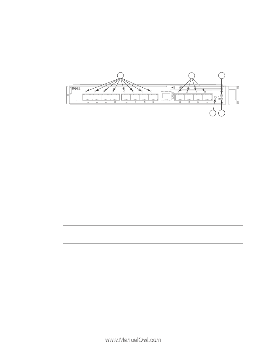
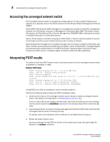
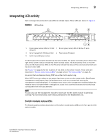
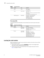
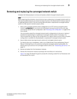
Interpreting LED activity 3 Interpreting LED activity Each converged network switch uses LEDs to indicate status. These LEDs are shown in Figure 4. FIGURE 4 LED Locations 1 2 3 M8428 -k 54 1 Bi-color (green/amber) LEDs for 10 GbE 2 Bi-color (green/amber) LEDs for 8 Gbps FC ports CEE ports 3 Server management LED (blue/amber) 4 Power status LED (green) 5 Switch status LED (green/amber) The front panel of the switch module has two sets of LEDs. The power and status/fault LEDs on the right of the switch module indicate the switch module status. The fault/activity LEDs on the CEE ports and the fault/activity LEDs on the FC ports indicate the status of the external ports. Each port has one bi-color LED. See Figure 4 on page 23 for the locations of the LEDs on the switch module. These LEDs are described in "Switch module status LEDs" on page 23 and "Port status LEDs" on page 24. Any errors that are detected during POST are written to the system log. When POST errors are written to the system log, these errors are also written to the BladeCenter management module event log. If a hardware error, such as a current fault occurs, the management module displays it. If a software error occurs, the management module displays the "Module did not complete POST" message and a post error code that indicates the test that was running when the error was detected. NOTE You can also use the management module to make sure that the switch module is operating correctly. For more information, see the documentation for the BladeCenter unit. Switch module status LEDs The following table provides descriptions of the switch module status LEDs on the front panel of the switch module. Dell M8428-k Hardware Reference Manual 23 53-1001980-01
-
 1
1 -
2
-
3
-
4
-
5
-
6
-
7
-
8
-
9
-
10
-
11
-
12
-
13
-
14
-
15
-
16
-
17
-
18
-
19
-
20
-
21
-
22
-
23
-
24
-
25
-
26
-
27
-
28
-
29
-
 30
30 -
 31
31 -
 32
32 -
 33
33 -
 34
34 -
 35
35 -
 36
36 -
 37
37 -
 38
38 -
 39
39 -
 40
40 -
41
-
42
-
43
-
44
-
45
-
46
-
47
-
48
-
49
-
50
-
51
-
52
-
53
-
54
 |
 |