Dell PowerEdge M520 Dell M8428-k Hardware Reference Manual - Page 37
Removing and replacing the converged network switch
 |
View all Dell PowerEdge M520 manuals
Add to My Manuals
Save this manual to your list of manuals |
Page 37 highlights
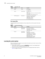
Removing and replacing the converged network switch 3 Removing and replacing the converged network switch Complete the following steps to remove and replace a failed converged network switch. NOTE Before beginning this procedure, ensure that you have a replacement converged network switch or filler panel available because you should not leave the slot on the Blade Server Enclosure open for an extended period of time. The slot must be filled with either a replacement converged network switch or a filler panel to maintain proper airflow. 1. Back up the converged network switch configuration to an FTP server by using the switch module's configUpload CLI command and following the prompts as well as the cmsh copy command to upload the CEE configuration. See "Backing up the configuration" on page 20 for more details. This commands upload the converged network switch configurations to the server, making it available for downloading to a replacement converged network switch if necessary. It is recommended that you back up the configuration on a regular basis to ensure that a complete configuration is available for downloading to a replacement converged network switch. 2. Stop all SAN activity requiring the ports used by the converged network switch. For details about port management, refer to your Blade Server EnclosureHardware Owner's Manual. Verify that there is no activity by viewing the converged network switch LEDs. For details about LED activity on the converged network switch, see "Interpreting LED activity" on page 23. 3. Remove all cables from the transceiver modules. 4. Remove the transceiver modules according to the manufacturer's instructions. Figure 5 on page 26 details the generic process for removing a cable from an transceiver and an transceiver from a port. Dell M8428-k Hardware Reference Manual 25 53-1001980-01
-
 1
1 -
2
-
3
-
4
-
5
-
6
-
7
-
8
-
9
-
10
-
11
-
12
-
13
-
14
-
15
-
16
-
17
-
18
-
19
-
20
-
21
-
22
-
23
-
24
-
25
-
26
-
27
-
28
-
29
-
30
-
31
-
 32
32 -
 33
33 -
 34
34 -
 35
35 -
 36
36 -
 37
37 -
 38
38 -
 39
39 -
 40
40 -
 41
41 -
 42
42 -
43
-
44
-
45
-
46
-
47
-
48
-
49
-
50
-
51
-
52
-
53
-
54
 |
 |