Dell PowerEdge M520 Brocade 4424 Blade Server SAN I/O Module Hardware Referenc - Page 14
Dell PowerEdge M520 Manual
 |
View all Dell PowerEdge M520 manuals
Add to My Manuals
Save this manual to your list of manuals |
Page 14 highlights
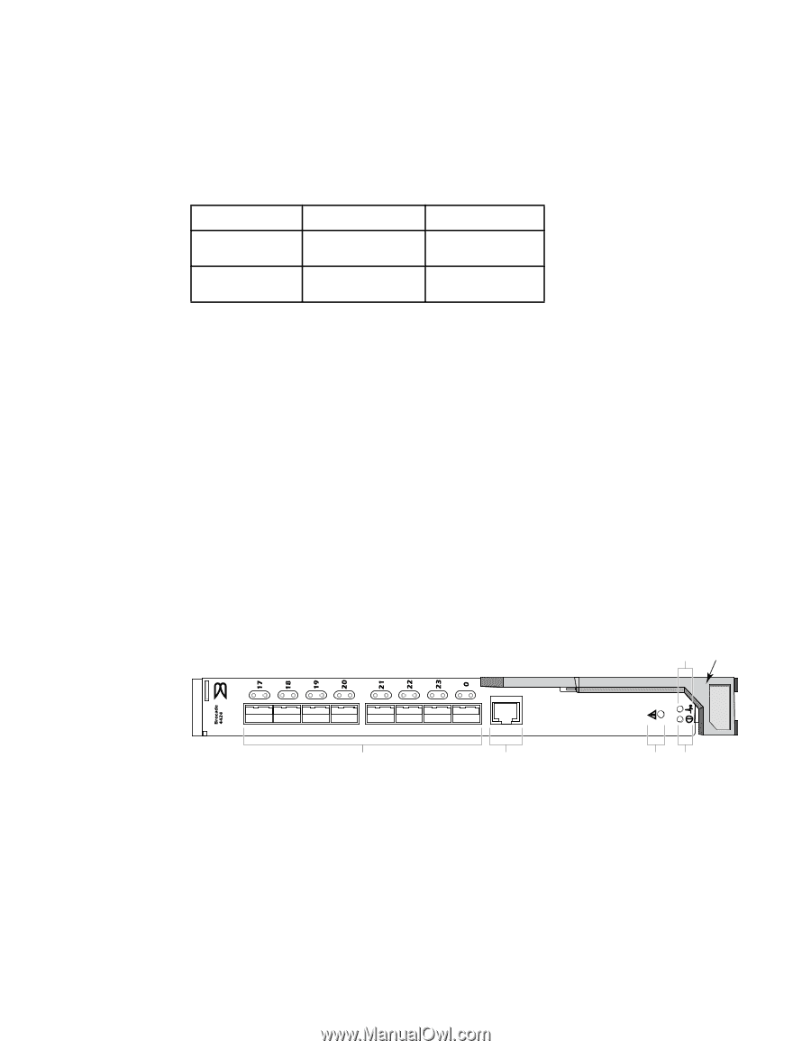
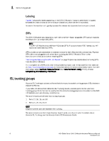
1 Hardware Description • For static POD, Table 1 shows the base internal and external ports that are licensed, as well as the additional 12 ports that can be activated with a POD license. For details about activating and deactivating additional ports when you have POD licensing, refer to "Activating Ports on Demand (POD)" on page 17. TABLE 1 Port Licensing Base POD Ports available External Ports 17, 18, 19, and 20 0, 21, 22, and 23 Internal Ports 1, 2, 3, 4, 5, 6, 7, and 8 9, 10, 11, 12, 13, 14, 15, and 16 Hardware Description This section describes the physical SAN I/O Module as shipped from the factory. For specifications, such as installed memory, weight and physical dimensions, facility requirements, architectural specifications, and regulatory compliance, refer to Appendix A, "SAN I/O Module specifications" Port side Externally accessible ports and LEDs are on the port side of the SAN I/O Module. The port side faces out when the SAN I/O Module is inserted into the I/O bay of the Blade Server enclosure. Figure 1 details the port side. For a complete description of the locations and interpretations of these LEDs, see "Interpreting LED activity" on page 22. Access the I/O module handle at the front of the port side of the SAN I/O Module. By lifting the handle's release latch, you can open the handle to remove and insert the unit from the Blade Server Enclosure. FIGURE 1 Port Side View 5 6 1 1. Ports with port status and port speed LEDs 2. RJ45 console port 3. SAN I/O Module status LED 4. Power status LED 5. Server management LED 6. SAN I/O Module handle 2 IOIOI 3 4 4 4424 Blade Server SAN I/O Module Hardware Reference Manual 53-0000571-01
-
 1
1 -
2
-
3
-
4
-
5
-
6
-
7
-
8
-
 9
9 -
 10
10 -
 11
11 -
 12
12 -
 13
13 -
 14
14 -
 15
15 -
 16
16 -
 17
17 -
 18
18 -
 19
19 -
20
-
21
-
22
-
23
-
24
-
25
-
26
-
27
-
28
-
29
-
30
-
31
-
32
-
33
-
34
-
35
-
36
-
37
-
38
-
39
-
40
-
41
-
42
-
43
-
44
-
45
-
46
-
47
-
48
 |
 |