Dell PowerEdge M520 Brocade 4424 Blade Server SAN I/O Module Hardware Referenc - Page 32
Dell PowerEdge M520 Manual
 |
View all Dell PowerEdge M520 manuals
Add to My Manuals
Save this manual to your list of manuals |
Page 32 highlights
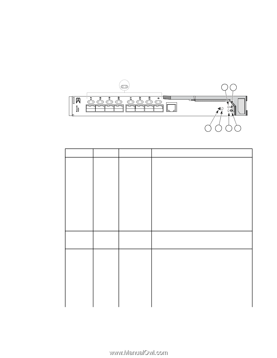
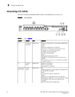
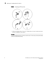
3 Interpreting LED activity Interpreting LED activity Each SAN I/O Module uses LEDs to indicate status. These LEDs are shown in Figure 5. FIGURE 5 LED Locations 1 2 7 8 IOIOI 3 4 5 6 TABLE 4 Location 1 Key to Figure 5 Indicator FC (external) port status Color green/amber Operation Note: LED meanings are not valid during boot, diagnostics, or POST. Green: Off (dark): No signal carrier or unlicensed. Steady: Online normal active port but no port activity. Flickering: normal active port (I/O activity). Slow blink: Online but segmented. Fast blink: Internal loopback. Amber Steady: Signal present but not online. Slow blink or flash: Disabled port (less than two second interval). Fast (rapid) blink or flash: Error or fault with port (less than 1/2 second interval). Amber on: 4 Gbit/sec FC Green on: 2 Gbit/sec FC Both off (dark): 1 Gbit/sec FC Off: SAN I/O Module is off or power supplies for the Blade Server or onboard DCC have failed. Green: No errors and all ports are ready for use. Amber: Steady: Boot-up state, port(s) offline, or in reset state. Blinking (green/amber): One or more environmental ranges are exceeded, or error log contains diagnostic error messages. Note: The LED might blink during testing. 2 FC port x speed module status green/amber 3 (status icon) and 4 (LED) green/amber 22 4424 Blade Server SAN I/O Module Hardware Reference Manual 53-0000571-01
-
 1
1 -
2
-
3
-
4
-
5
-
6
-
7
-
8
-
9
-
10
-
11
-
12
-
13
-
14
-
15
-
16
-
17
-
18
-
19
-
20
-
21
-
22
-
23
-
24
-
25
-
26
-
 27
27 -
 28
28 -
 29
29 -
 30
30 -
 31
31 -
 32
32 -
 33
33 -
 34
34 -
 35
35 -
 36
36 -
 37
37 -
38
-
39
-
40
-
41
-
42
-
43
-
44
-
45
-
46
-
47
-
48
 |
 |