Dell PowerEdge M520 Brocade 4424 Blade Server SAN I/O Module Hardware Referenc - Page 15
Dell PowerEdge M520 Manual
 |
View all Dell PowerEdge M520 manuals
Add to My Manuals
Save this manual to your list of manuals |
Page 15 highlights
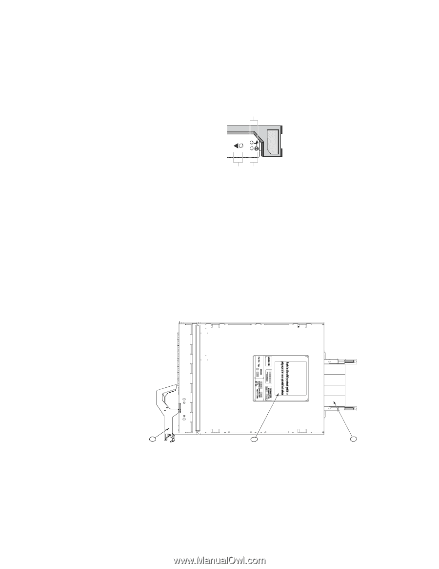
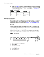
Hardware Description 1 The nonport (SAN I/O Module status) LEDs, shown as item 3 of Figure 1, display SAN I/O Module-level information as shown in Figure 2. FIGURE 2 Other Status LEDs 3 1 1 2 3 SAN I/O Module status LED Power status LED Server Management LED 2 Nonport side The nonport side of the SAN I/O Module (shown in Figure 3) is seated into the enclosure. You do not need to line up the SAN I/O Module as it will seat correctly when the insertion arm is closed. When the SAN I/O Module is inserted, the backplane connectors activate a connection port, allowing the SAN I/O Module to be configured in the Blade Server Enclosure. FIGURE 3 Nonport Side, Viewed from Top 1 2 3 1. I/O module handle. Lifting the handle's release latch opens the handle to install and remove the module from the Blade Server Enclosure. 2. Product label including serial number. 3. Connectors 4424 Blade Server SAN I/O Module Hardware Reference Manual 53-0000571-01 5
-
 1
1 -
2
-
3
-
4
-
5
-
6
-
7
-
8
-
9
-
 10
10 -
 11
11 -
 12
12 -
 13
13 -
 14
14 -
 15
15 -
 16
16 -
 17
17 -
 18
18 -
 19
19 -
 20
20 -
21
-
22
-
23
-
24
-
25
-
26
-
27
-
28
-
29
-
30
-
31
-
32
-
33
-
34
-
35
-
36
-
37
-
38
-
39
-
40
-
41
-
42
-
43
-
44
-
45
-
46
-
47
-
48
 |
 |