Dell PowerEdge MX740c EMC PowerEdge MX7000 Enclosure Installation and Service - Page 16
Back view of the enclosure
 |
View all Dell PowerEdge MX740c manuals
Add to My Manuals
Save this manual to your list of manuals |
Page 16 highlights
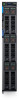
Figure 9. Rear fan module Table 6. Fan module indicator codes Fan indicators Fan functioning normally - Front/ Rear Fan failure Indicator state Solid green Blinks amber 2 seconds and 1 second OFF NOTE: When the chassis is powered off with the AC connection that is powered on, only the rear fans are powered off. Back view of the enclosure Figure 10. Back view of the enclosure 1. Slot for Fabric A1 3. Rear fans (5) 5. Slot for Fabric B2 7. Power cable connection status LED 9. Management Module 2 11. Slot for Fabric C1 2. Slot for Fabric A2 4. Slot for Fabric B1 6. Slot for Fabric C2 8. C22 Power inlet connectors (6) 10. Management Module 1 NOTE: For more information about the ports and connectors, see Technical specifications. 16 Enclosure overview
-
 1
1 -
2
-
3
-
4
-
5
-
6
-
7
-
8
-
9
-
10
-
 11
11 -
 12
12 -
 13
13 -
 14
14 -
 15
15 -
 16
16 -
 17
17 -
 18
18 -
 19
19 -
 20
20 -
 21
21 -
22
-
23
-
24
-
25
-
26
-
27
-
28
-
29
-
30
-
31
-
32
-
33
-
34
-
35
-
36
-
37
-
38
-
39
-
40
-
41
-
42
-
43
-
44
-
45
-
46
-
47
-
48
-
49
-
50
-
51
-
52
-
53
-
54
-
55
-
56
-
57
-
58
-
59
-
60
-
61
-
62
-
63
 |
 |
