Dell PowerEdge R940 Deploying the 385TB Data Warehouse Fast Track Reference Ar - Page 7
Cabling requirements
 |
View all Dell PowerEdge R940 manuals
Add to My Manuals
Save this manual to your list of manuals |
Page 7 highlights
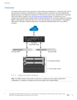
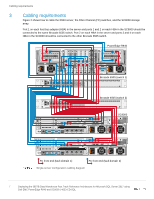
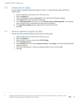
Cabling requirements 3 Cabling requirements Figure 2 shows how to cable the R940 server, the Fibre Channel (FC) switches, and the SC9000 storage array. Port 1 on each host bus adapter (HBA) in the server and ports 1 and 2 on each HBA in the SC9000 should be connected to the same Brocade 6505 switch. Port 2 on each HBA in the server and ports 3 and 4 on each HBA in the SC9000 should be connected to the other Brocade 6505 switch. PORT 1 842 842 PORT 2 PCIe x8 8Gb FC PCIe x8 8Gb FC PCIe x8 8Gb FC PCIe x8 8Gb FC PORT 1 842 PORT 1 842 PORT 1 842 PORT 1 842 PORT 1 842 PowerEdge R940 PCIe x8 8Gb FC PCIe x8 8Gb FC 842 PORT 2 842 PORT 2 PORT 1 842 PORT 1 842 842 PORT 2 842 PORT 2 842 PORT 2 842 PORT 2 842 PORT 2 Brocade 6505 04 15 26 37 8 12 9 13 10 14 11 15 16 20 17 21 18 22 19 23 Brocade 6505 (switch 1) TX RX TX RX PCIe x8 8Gb FC TX RX TX RX PCIe x8 8Gb FC PCIe x8 8Gb FC PCIe x8 8Gb FC Brocade 6505 04 15 26 37 8 12 9 13 10 14 11 15 16 20 17 21 18 22 19 23 Brocade 6505 (switch 2) 1 2 3 iDRAC 6 1234 PORTS 4 842 842 842 842 PCIe x8 8Gb FC PORT C1 PORT C2 1234 PORTS CA CH E 5 7 1 1 2 3 4 1100W 842 PORT 2 PORT 1 842 842 842 842 842 PCIe x8 8Gb FC PCIe x8 SC9000 2 1100W 842 842 842 842 PCIe x8 8Gb FC 1 2 3 iDRAC 1234 6 PORTS 4 842 842 842 842 PCIe x8 8Gb FC PORT C1 PORT C2 1234 PORTS CA CH E 5 7 1 1 2 3 4 1100W 842 PORT 2 PORT 1 842 PCIe x8 2 1100W FC front end (fault domain 1) FC front end (fault domain 2) Single-server configuration cabling diagram 7 Deploying the 385TB Data Warehouse Fast Track Reference Architecture for Microsoft SQL Server 2017 using Dell EMC PowerEdge R940 and SC9000 | 4033-CD-SQL
-
 1
1 -
 2
2 -
 3
3 -
 4
4 -
 5
5 -
 6
6 -
 7
7 -
 8
8 -
 9
9 -
 10
10 -
 11
11 -
 12
12 -
13
-
14
-
15
-
16
-
17
-
18
-
19
-
20
-
21
-
22
-
23
-
24
-
25
 |
 |
