Dell PowerVault 51F Dell PowerVault 51F 8-Port Fibre Channel Switch Insta - Page 40
Replacing the Doors on the Rack, Stand-Alone Mounting
 |
View all Dell PowerVault 51F manuals
Add to My Manuals
Save this manual to your list of manuals |
Page 40 highlights
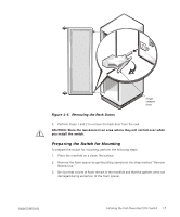
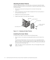
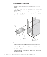
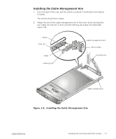
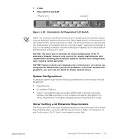
3. Route the cables along the cable-management arm and secure the cables to the cable-management arm with the Velcro straps attached to the cablemanagement arm. Make sure that the cables are not pinched in the cable-management arm joints. 4. Press the safety release latch on the inner rails and slide the switch into the rack until it snaps into place. Be sure the surfaces between the manifold and the switch are flush. 5. Tighten the thumbscrew on the cable-management arm. The thumbscrew passes through the hold in the rack and into the middle hold of the adjustable bracket. Replacing the Doors on the Rack To replace the rack's front and back doors, perform the following steps. CAUTION: To prevent personal injury due to the size and weight of the doors, never attempt to replace the doors by yourself. 1. Lift the front door into position, and align the hinges with the holes in the rack (see Figure 1-4). 2. Slide the hinges into the holes in the rack until the hinge release levers lock the hinges into position. 3. Close the door latch by rotating the handle counterclockwise until it stops, push the handle in until it locks in position, and then slide the push-button cover down over the push button (see Figure 1-3). Repeat steps 1 through 3 to install the back door. Stand-Alone Mounting The switch is shipped in its stand-alone configuration. Adhesive rubber feet are supplied if the switch is surface-mounted. Installation of the rubber feet is optional, and is not required for proper or safe switch operation. To install the adhesive rubber feet, perform the following steps: 1. Use the alcohol wipes provided to clean the four depressions at each corner of the chassis bottom. Allow the alcohol to dry. 2. Remove the rubber feet from the backing sheet and place one in each depression. 3. Firmly press the rubber feet in place. NOTE: If rubber feet have been installed, they must be removed before the unit can be installed in a 19-inch rack. 1-12 Dell PowerVault 51F 8-Port Fibre Channel Switch Installation and Troubleshooting Guide
-
 1
1 -
2
-
3
-
4
-
5
-
6
-
7
-
8
-
9
-
10
-
11
-
12
-
13
-
14
-
15
-
16
-
17
-
18
-
19
-
20
-
21
-
22
-
23
-
24
-
25
-
26
-
27
-
28
-
29
-
30
-
31
-
32
-
33
-
34
-
 35
35 -
 36
36 -
 37
37 -
 38
38 -
 39
39 -
 40
40 -
 41
41 -
 42
42 -
 43
43 -
 44
44 -
 45
45 -
46
-
47
-
48
-
49
-
50
-
51
-
52
-
53
-
54
-
55
-
56
-
57
-
58
-
59
-
60
-
61
-
62
-
63
-
64
-
65
-
66
-
67
-
68
-
69
-
70
-
71
-
72
-
73
-
74
-
75
-
76
-
77
-
78
-
79
-
80
-
81
-
82
-
83
-
84
-
85
-
86
-
87
-
88
-
89
-
90
-
91
-
92
-
93
-
94
-
95
-
96
-
97
-
98
-
99
-
100
-
101
-
102
-
103
-
104
-
105
-
106
-
107
-
108
-
109
-
110
-
111
-
112
-
113
-
114
-
115
-
116
-
117
-
118
-
119
-
120
-
121
-
122
-
123
-
124
-
125
-
126
-
127
-
128
-
129
-
130
-
131
-
132
-
133
-
134
-
135
-
136
-
137
-
138
-
139
-
140
-
141
-
142
-
143
-
144
-
145
-
146
-
147
-
148
-
149
-
150
-
151
-
152
-
153
-
154
-
155
-
156
 |
 |
