Dell S4148U-ON EMC PowerSwitch S4100–ON Series Installation Guide M - Page 34
AC or DC power supply installation, PSU LEDs
 |
View all Dell S4148U-ON manuals
Add to My Manuals
Save this manual to your list of manuals |
Page 34 highlights
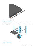
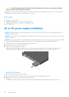
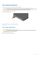
CAUTION: Remove the power cable from the PSU before removing the PSU. Also, do not connect the power cable before you insert the PSU in the switch. NOTE: To comply with the GR-1089 Lightning Criteria for Equipment Interfacing with AC Power Ports, use an external surge protection device (SPD) at the AC input of the router. PSU LEDs ● Solid green-Input is OK. ● Flashing yellow (amber)-There is a fault with the PSU. ● Flashing green blink at 1Hz-Switch is in standby/CR state. ● Off-PSU is off. AC or DC power supply installation NOTE: The PSU slides into the slot smoothly. Do not force a PSU into a slot as this action may damage the PSU or the S4100-ON Series switch. NOTE: Ensure that you correctly install the PSU. When you install the PSU correctly, the power connector is on the right side of the PSU. NOTE: If you use a single PSU, install a blank plate in the other PSU slot. If you are only using one power supply, Dell EMC recommends installing the power supply in the first slot, PSU1. Install a blank plate in the second slot, PSU2. 1. Remove the PSU slot cover using a small #1 Phillips screwdriver. 2. Remove the PSU from the electro-static bag. 3. Insert the PSU into the switch PSU slot. Insert the exposed PCB edge connector first. The PSU slot is keyed so that the PSU can only be fully inserted in one orientation. When you install the PSU correctly, it snaps into place and is flushed with the back of the switch. Figure 24. PSU installation a. Left PSU is PSU1 and right PSU is PSU2. 4. Plug in the appropriate AC 3-prongs cord from the switch PSU to the external power source. 5. Repeat steps 1 through 4 if you have a redundant PSU slot. NOTE: The switch powers up when you connect the cables between the power supply and the power source. 34 Power supplies
-
 1
1 -
2
-
3
-
4
-
5
-
6
-
7
-
8
-
9
-
10
-
11
-
12
-
13
-
14
-
15
-
16
-
17
-
18
-
19
-
20
-
21
-
22
-
23
-
24
-
25
-
26
-
27
-
28
-
 29
29 -
 30
30 -
 31
31 -
 32
32 -
 33
33 -
 34
34 -
 35
35 -
 36
36 -
 37
37 -
 38
38 -
 39
39 -
40
-
41
-
42
-
43
-
44
-
45
-
46
-
47
-
48
-
49
 |
 |
