Dell S4148U-ON EMC PowerSwitch S4100–ON Series Installation Guide M - Page 35
AC or DC power supply replacement, DC power supply connection
 |
View all Dell S4148U-ON manuals
Add to My Manuals
Save this manual to your list of manuals |
Page 35 highlights
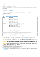
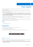
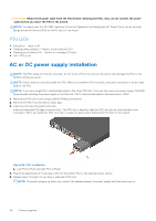
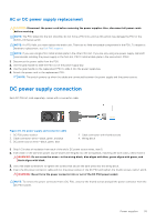
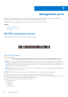
AC or DC power supply replacement CAUTION: Disconnect the power cord before removing the power supplies. Also, disconnect all power cords before servicing. NOTE: The PSU slides into the slot smoothly. Do not force a PSU into a slot as this action may damage the PSU or the S4100-ON Series switch. NOTE: If a PSU fails, you must replace the entire unit. There are no field serviceable components in the PSU. To request a hardware replacement, see Dell EMC support. NOTE: If you use a single PSU, install a blank plate in the other PSU slot. If you are only using one power supply, Dell EMC recommends installing the power supply in the first slot, PSU1. Install a blank plate in the second slot, PSU2. 1. Disconnect the power cable from the PSU. 2. Use the grab handle to slide the PSU out of the power supply bay. 3. Use the grab handle on the replacement PSU to slide it into the power supply bay. 4. Attach the power cord to the replacement PSU. NOTE: The switch powers up when the cables are connected between the power supply and the power source. DC power supply connection Each DC PSU kit, sold separately, comes with a connector cable. Figure 25. DC power supply and connector cable 1. DC PSU power socket 3. Cable connector wires-black, green, and blue 5. DC power source wires-black, green, blue 2. Cable connector with thumb screws 4. Wiring block 1. Strip 1/2 inches of insulation from each of the site's DC power source wires, item 5. 2. Insert each of the site's DC power source's bare wire lengths into the wiring block, matching the wire colors, items 3 and 4. WARNING: Do not cross the wires-in the wiring block, blue aligns with blue, green aligns with green, and black aligns with black. 3. Use a flat-blade screwdriver to tighten the screws that secure the bare wires into the wiring block. 4. Insert the DC power connector cable end into the power socket of the DC PSU and tighten the thumb screws, items 1 and 2. WARNING: Never force the power connector into or out of the DC PSU power socket. NOTE: To remove the power connector from a DC PSU, unscrew the thumb screws and pull the power connector from the DC PSU socket. Power supplies 35
-
 1
1 -
2
-
3
-
4
-
5
-
6
-
7
-
8
-
9
-
10
-
11
-
12
-
13
-
14
-
15
-
16
-
17
-
18
-
19
-
20
-
21
-
22
-
23
-
24
-
25
-
26
-
27
-
28
-
29
-
 30
30 -
 31
31 -
 32
32 -
 33
33 -
 34
34 -
 35
35 -
 36
36 -
 37
37 -
 38
38 -
 39
39 -
 40
40 -
41
-
42
-
43
-
44
-
45
-
46
-
47
-
48
-
49
 |
 |
