Dell Studio 15 Dell Studio 1555 Service Manual - Page 12
Before You Begin, Replacing the Processor Heat Sink, Back to Contents
 |
View all Dell Studio 15 manuals
Add to My Manuals
Save this manual to your list of manuals |
Page 12 highlights
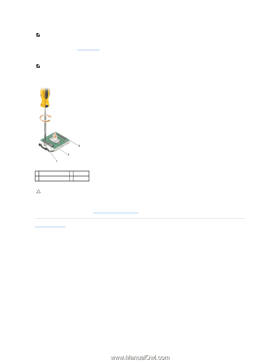
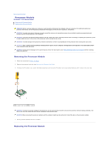
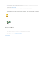
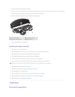
NOTE: If a new processor is installed, you will receive a new thermal-cooling assembly, which will include an affixed thermal pad, or you will receive a new thermal pad along with documentation to illustrate proper installation. 1. Follow the instructions in Before You Begin. 2. Align the pin-1 corner of the processor module with the pin-1 corner of the ZIF socket, then insert the processor module. NOTE: The pin-1 corner of the processor module has a triangle that aligns with the triangle on the pin-1 corner of the ZIF socket. When the processor module is properly seated, all four corners are aligned at the same height. If one or more corners of the module are higher than the others, the module is not seated properly. 1 ZIF-socket cam screw 2 ZIF socket 3 pin-1 corner CAUTION: To avoid damage to the processor, hold the screwdriver so that it is perpendicular to the processor when turning the cam screw. 3. Tighten the ZIF socket by turning the cam screw clockwise to secure the processor module to the system board. 4. Replace the processor heat sink (see Replacing the Processor Heat Sink). Back to Contents Page
-
 1
1 -
2
-
3
-
4
-
5
-
6
-
 7
7 -
 8
8 -
 9
9 -
 10
10 -
 11
11 -
 12
12 -
 13
13 -
 14
14 -
 15
15 -
 16
16 -
 17
17 -
18
-
19
-
20
-
21
-
22
-
23
-
24
-
25
-
26
-
27
-
28
-
29
-
30
-
31
-
32
-
33
-
34
-
35
-
36
-
37
-
38
-
39
-
40
-
41
-
42
-
43
-
44
-
45
-
46
-
47
-
48
-
49
 |
 |