Dell Vostro 270 Owner's Manual - Page 26
Installing the System Board, SATA connectors SATA0, SATA1 - mini
 |
View all Dell Vostro 270 manuals
Add to My Manuals
Save this manual to your list of manuals |
Page 26 highlights
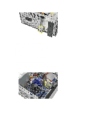
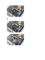
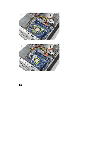
1. SATA connectors (SATA0, SATA1, SATA2, SATA3) 2. front USB connector 3. front USB Connector 4. password reset jumper 5. audio connector 6. PCI Express x1 card slot 7. CMOS (coin-cell) battery 8. PCI Express x16 card slot 9. system fan connector 10. power connector 11. processor socket 12. processor fan connector 13. memory module connectors (DIMM 1 and 2) 14. main power connector 15. CMOS clear reset jumper 16. PCI Express-mini connector 17. front LED power connector Installing the System Board 1. Place the system board into the computer and then slide it towards the back of the computer. 2. Replace the screws to secure the system board to the computer. 3. Connect all the cables to the system board. 4. Replace the: 26
-
 1
1 -
2
-
3
-
4
-
5
-
6
-
7
-
8
-
9
-
10
-
11
-
12
-
13
-
14
-
15
-
16
-
17
-
18
-
19
-
20
-
 21
21 -
 22
22 -
 23
23 -
 24
24 -
 25
25 -
 26
26 -
 27
27 -
 28
28 -
 29
29 -
 30
30 -
 31
31 -
32
-
33
-
34
-
35
-
36
-
37
-
38
-
39
-
40
-
41
-
42
-
43
-
44
-
45
-
46
-
47
-
48
-
49
-
50
-
51
 |
 |
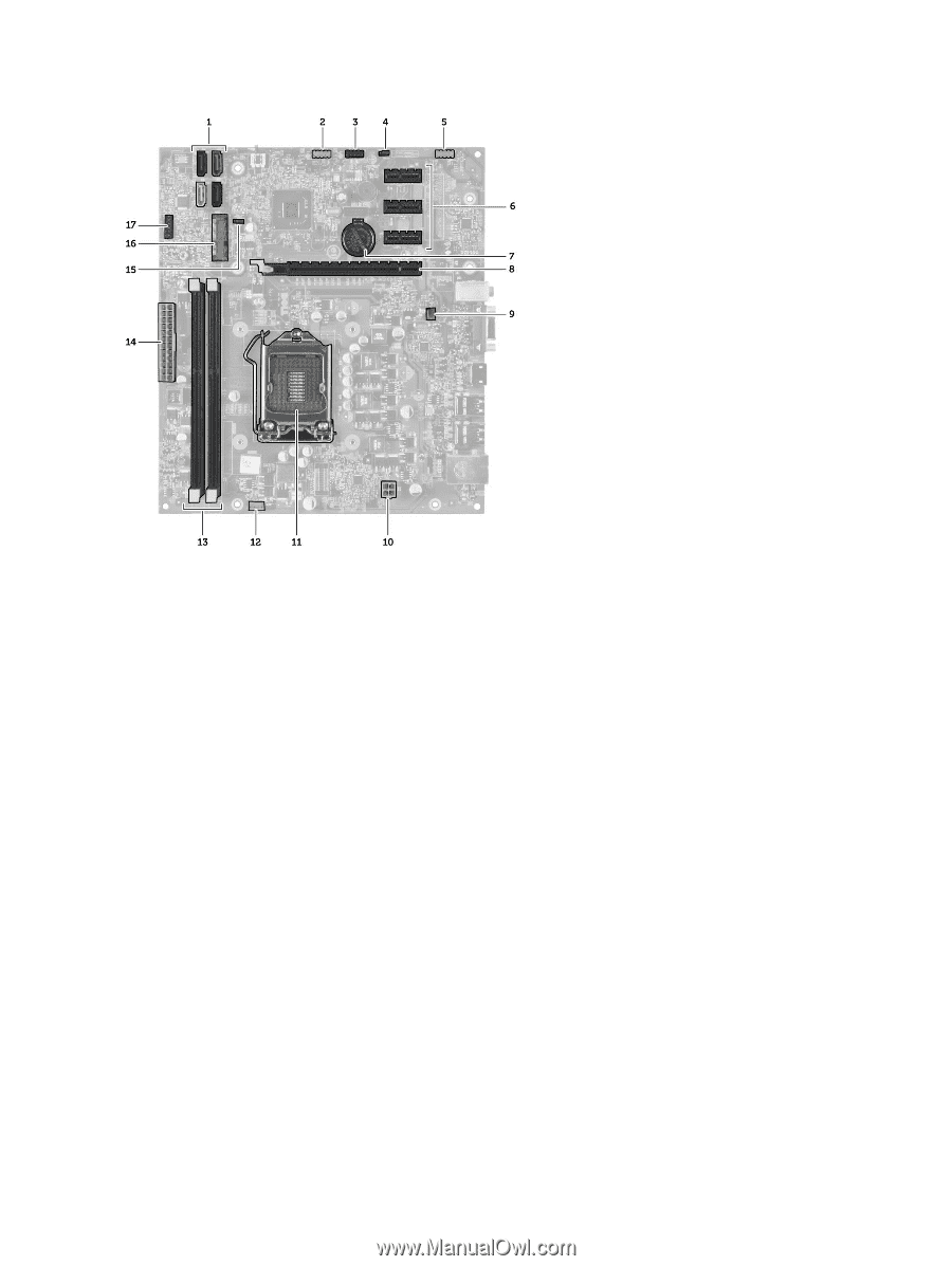
1. SATA connectors (SATA0, SATA1, SATA2, SATA3)
2. front USB connector
3. front USB Connector
4. password reset jumper
5. audio connector
6. PCI Express x1 card slot
7. CMOS (coin-cell) battery
8. PCI Express x16 card slot
9. system fan connector
10. power connector
11. processor socket
12. processor fan connector
13. memory module connectors (DIMM 1 and 2)
14. main power connector
15. CMOS clear reset jumper
16. PCI Express-mini connector
17. front LED power connector
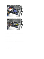
Installing the System Board
1.
Place the system board into the computer and then slide it towards the back of the computer.
2.
Replace the screws to secure the system board to the computer.
3.
Connect all the cables to the system board.
4.
Replace the:
26