Dell Vostro 3582 Service Manual with optical drive
Dell Vostro 3582 Manual
 |
View all Dell Vostro 3582 manuals
Add to My Manuals
Save this manual to your list of manuals |
Dell Vostro 3582 manual content summary:
- Dell Vostro 3582 | Service Manual with optical drive - Page 1
Vostro 3582 Service Manual (with optical drive) Regulatory Model: P75F Regulatory Type: P75F011 - Dell Vostro 3582 | Service Manual with optical drive - Page 2
and tells you how to avoid the problem. WARNING: A WARNING indicates a potential for property damage, personal injury, or death. © 2018 - 2019 Dell Inc. or its subsidiaries. All rights reserved. Dell, EMC, and other trademarks are trademarks of Dell Inc. or its subsidiaries. Other trademarks may - Dell Vostro 3582 | Service Manual with optical drive - Page 3
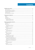
instructions...6 Before working inside your computer...6 Electrostatic discharge-ESD protection...7 Transporting sensitive components...7 ESD field service installing components 15 Recommended tools...15 Screw list...15 Micro SD M2. SATA Solid State Drive (SSD)...27 Removing the M.2 2280 solid - Dell Vostro 3582 | Service Manual with optical drive - Page 4
Installing the touchpad...35 Hard drive assembly...37 Removing the hard drive assembly...37 Installing the hard drive assembly...38 Hard drive...39 Removing the hard drive ...39 Installing the hard drive ...40 WLAN card...41 Removing the WLAN card...41 Installing the WLAN card...42 Coin-cell battery - Dell Vostro 3582 | Service Manual with optical drive - Page 5
assembly...80 Removing the palmrest and keyboard assembly...80 4 Troubleshooting...82 Enhanced Pre-Boot System Assessment (ePSA) diagnostics 82 the ePSA diagnostics...82 System diagnostic lights...82 Flashing BIOS (USB key)...83 Flashing the BIOS...84 Backup media and recovery options...84 WiFi - Dell Vostro 3582 | Service Manual with optical drive - Page 6
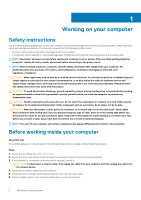
only perform troubleshooting and simple repairs as authorized in your product documentation, or as directed by the online or telephone service and support team. Damage due to servicing that is not authorized by Dell is not covered by your warranty. Read and follow the safety instructions that came - Dell Vostro 3582 | Service Manual with optical drive - Page 7
battery before you service the computer. , such as intermittent problems or a shortened product of damage to recognize and troubleshoot is the intermittent (also returned to Dell, it is toes out. 2. Tighten stomach muscles. Abdominal muscles support your spine when you lift, offsetting the force - Dell Vostro 3582 | Service Manual with optical drive - Page 8
grounding wrist strap and protective anti-static mat at all times when servicing Dell products. In addition, it is critical that technicians keep sensitive parts separate from all insulator parts while performing service and that they use anti-static bags for transporting sensitive components. After - Dell Vostro 3582 | Service Manual with optical drive - Page 9
CAUTION: To avoid damage to the computer, use only the battery designed for this particular Dell computer. Do not use batteries designed for other Dell computers. Steps 1. Connect any external devices, such as a port replicator or media base, and replace any cards, such as an ExpressCard. 2. Connect - Dell Vostro 3582 | Service Manual with optical drive - Page 10
2 Technology and components NOTE: Instructions provided in this section are applicable on computers shipped 1.2 volts, compared to DDR3 which requires 1.5 volts of electrical power to operate. DDR4 also supports a new, deep power-down mode that allows the host device to go into standby without - Dell Vostro 3582 | Service Manual with optical drive - Page 11
code. If all memory fails, the LCD does not turn on. Troubleshoot for possible memory failure by trying known good memory modules in the primary advantage is cable reduction and content protection provisions. HDMI supports standard, enhanced, or high-definition video, plus multichannel digital - Dell Vostro 3582 | Service Manual with optical drive - Page 12
bus power and increased device current draw to better accommodate power-hungry devices • New power management features • Full-duplex data transfers and support for new transfer types • Backward USB 2.0 compatibility • New connectors and cable The topics below cover some of the most commonly asked - Dell Vostro 3582 | Service Manual with optical drive - Page 13
on USB 3.0/USB 3.1 Gen 1 cables and only come into contact when connected to a proper SuperSpeed USB connection. Windows 10 will be bringing native support for USB 3.1 Gen 1 controllers. This is in contrast to previous versions of Windows, which continue to require separate drivers for USB 3.0/USB - Dell Vostro 3582 | Service Manual with optical drive - Page 14
Windows 10 64-bit version or higher • Intel Rapid Storage Technology driver version 15.9.1.1018 or higher Table 2. Intel Optane memory specifications Feature Interface Connector Configurations supported Capacity Specifications PCIe 3x2 NVMe 1.1 M.2 card slot (2230/2280) • 7th Generation or higher - Dell Vostro 3582 | Service Manual with optical drive - Page 15
Display panel Display hinges Touchpad M2x2 2 M2x3 4 M2x3 4 M3x3 4 M2x2 Big Head 1 M2x3 2 M2x3 1 M2.5x5 5 M2x2 4 M2.5x2.5 8 M2x2 2 M2x2 4 Removing and installing components 15 - Dell Vostro 3582 | Service Manual with optical drive - Page 16
Component Power button board Fingerprint-reader Thermal plate Power-adapter port I/O board Power button Solid-state drive System board Wireless-antenna bracket Screw type M2x3 M2x2 M2x3 M2x3 M2x4 M2x2 M2x2 M2x4 M2x4 Quantity 1 1 2 1 1 1 1 1 2 Micro SD card Removing the micro SD card - Dell Vostro 3582 | Service Manual with optical drive - Page 17
Installing the micro SD card Steps Slide the micro Secure Digital into the slot until it clicks into place. Removing and installing components 17 - Dell Vostro 3582 | Service Manual with optical drive - Page 18
Next steps 1. Follow the procedure in after working inside your computer. Optical drive Removing the optical drive Steps 1. Remove the screw (M2x2) that secures the optical-drive assembly to the base cover [1]. 2. Slide the optical-drive assembly out of the optical-drive bay [2]. 3. Remove the two - Dell Vostro 3582 | Service Manual with optical drive - Page 19
Installing optical drive Steps 1. Align the optical drive bracket to the screw holes on the optical drive [1]. 2. Replace the two (M2x3) screws that secure the optical drive bracket [2]. 3. Slide the optical-drive assembly into the optical-drive bay [1]. 4. Replace the screw (M2x2) that secures the - Dell Vostro 3582 | Service Manual with optical drive - Page 20
Next steps 1. Install the SD card. 2. Follow the procedures in After working inside your computer. Base cover Removing the base cover Prerequisites 1. Follow the procedure in Before working inside your computer. 2. Remove the SD card. 3. Remove the optical drive. Steps 1. Loosen the three captive - Dell Vostro 3582 | Service Manual with optical drive - Page 21
5. Pry the base cover from the top-right corner and continue doing it throughout [1,2]. 6. Lift the base cover from the system [3]. Removing and installing components 21 - Dell Vostro 3582 | Service Manual with optical drive - Page 22
Installing the base cover Steps 1. Place the base cover on the palmrest and keyboard assembly [1]. 2. Press on the right side of the base cover till it snaps into place [2, 3] 3. Tighten the three captive screws that secure the base cover to the palmrest and keyboard assembly [1]. 4. Replace the - Dell Vostro 3582 | Service Manual with optical drive - Page 23
Next steps 1. Install the optical drive 2. Install the SD card 3. Follow the procedure in after working inside your computer Battery Removing the battery Steps 1. Follow the procedure in Before working inside your computer. 2. Remove the base cover. 3. Disconnect the battery cable from the connector - Dell Vostro 3582 | Service Manual with optical drive - Page 24
Installing the battery Steps 1. Align the screw holes on the battery with the screw holes on the palm rest assembly [1]. 2. Replace the four screws to secure the battery to the system [2]. 3. Connect the battery cable to its connector on the system board [3]. 24 Removing and installing components - Dell Vostro 3582 | Service Manual with optical drive - Page 25
Next steps 1. Install the Base cover: 2. Follow the procedures in After working inside your computer. Memory modules Removing the memory module Prerequisites 1. Follow the procedure in Before working inside your computer. 2. Remove the SD card. 3. Remove the optical drive. 4. Remove the base cover. - Dell Vostro 3582 | Service Manual with optical drive - Page 26
Installing the memory module Steps 1. Insert the memory module into the memory socket [1]. 2. Press the memory module until the clips secure the memory module [2]. 26 Removing and installing components - Dell Vostro 3582 | Service Manual with optical drive - Page 27
your computer. 2. Remove the SD card. 3. Remove the optical drive. 4. Remove the base cover. 5. Remove the battery Steps 1. Loosen the captive screws that secure the SSD thermal plate and solid-state drive to the palm rest and keyboard assembly [1]. 2. Remove the single (M2x3) screw that secures the - Dell Vostro 3582 | Service Manual with optical drive - Page 28
M.2 2280 Solid state drive Steps 1. Slide and insert the solid-state drive into the solid-state drive slot [1]. 2. Place the thermal pad on the SSD as shown in the image [2]. 3. Tighten the captive screw that secures the thermal plate to the palmrest and keyboard assembly [3]. 4. Replace the single - Dell Vostro 3582 | Service Manual with optical drive - Page 29
your computer. 2. Remove the SD card. 3. Remove the optical drive. 4. Remove the base cover. 5. Remove the battery Steps 1. Loosen the captive screws that secure the SSD thermal plate and solid-state drive to the palm rest and keyboard assembly [1]. 2. Remove the screw that secures the - Dell Vostro 3582 | Service Manual with optical drive - Page 30
4. Turn the thermal plate over. 5. Remove the (M2x2) screw that secures the solid-state drive to the thermal plate [1]. 6. Lift the solid-state drive off the thermal plate [2]. Installing the M.2 2230 Solid state drive Steps 1. Place the solid-state drive into the slot of the thermal plate [1] 2. - Dell Vostro 3582 | Service Manual with optical drive - Page 31
3. Slide and insert the solid-state drive thermal plate into the solid-state drive slot [1]. 4. Tighten the captive screw that secures the thermal plate to the palmrest and keyboard assembly [2]. 5. Replace the (M2x3) screw that secures the thermal plate to the palmrest and keyboard assembly [3]. - Dell Vostro 3582 | Service Manual with optical drive - Page 32
I/O board Removing the I/O board Steps 1. Open the latch and disconnect the I/O-board cable from the system board [1]. 2. Remove the screw (M2x4) that secures the I/O board to the palm rest and keyboard assembly [2]. 3. Lift the I/O board off the palm rest and keyboard assembly [3]. Installing the - Dell Vostro 3582 | Service Manual with optical drive - Page 33
Touchpad Removing the touchpad Prerequisites 1. Follow the procedure in Before working inside your computer. 2. Remove the SD card. 3. Remove the optical drive. 4. Remove the base cover. 5. Remove the battery Steps 1. Open the latch and disconnect the hard-drive cable from the system board [1]. 2. - Dell Vostro 3582 | Service Manual with optical drive - Page 34
4. Remove the two screws (M2x2) that secure the touchpad bracket to the system [1]. 5. Lift the touchpad bracket off the system [2] 6. Remove the four screws (M2x2) that secure the touchpad to the palm rest and keyboard assembly [1]. 7. Lift the touchpad off the palm rest and keyboard assembly [2]. - Dell Vostro 3582 | Service Manual with optical drive - Page 35
Installing the touchpad About this task NOTE: Ensure that the touchpad is aligned with the guides available on the palm-rest and keyboard assembly, and the gap on either sides of the touchpad is equal. Steps 1. Place the touchpad into the - Dell Vostro 3582 | Service Manual with optical drive - Page 36
3. Align and place the touchpad bracket with the screw holes on the palm-rest and keyboard assembly [1]. 4. Replace the two screws (M2x2) to secure the touchpad bracket to the palm-rest and keyboard assembly [2] 5. Affix the tape that secures the touchpad to the palm rest and keyboard assembly [1]. - Dell Vostro 3582 | Service Manual with optical drive - Page 37
Next steps 1. Install the battery. 2. Install the base cover. 3. Install the optical drive. 4. Install the SD card. 5. Follow the procedures in After working inside your computer. Hard drive assembly Removing the hard drive assembly Prerequisites 1. Follow the procedure in Before working inside your - Dell Vostro 3582 | Service Manual with optical drive - Page 38
Installing the hard drive assembly Steps 1. Align the screw holes on the hard drive assembly with the screw holes on the palm rest and keyboard assembly [1]. 2. Replace the four screws (M2x3) that secure the hard drive assembly to the palm rest and keyboard assembly [2]. 3. Connect the hard drive - Dell Vostro 3582 | Service Manual with optical drive - Page 39
Next steps 1. Install the battery. 2. Install the base cover. 3. Install the optical drive. 4. Install the SD card. 5. Follow the procedures in After working inside your computer. Hard drive Removing the hard drive Prerequisites 1. Follow the procedure in Before working inside your computer. 2. - Dell Vostro 3582 | Service Manual with optical drive - Page 40
2. Remove the four screws (M3x3) that secure the hard drive bracket to the hard drive [1]. 3. Lift the hard drive bracket off the hard drive [2]. Installing the hard drive Steps 1. Align the screw holes on the hard drive bracket with the screw holes on the hard drive [1]. 2. Replace the four screws - Dell Vostro 3582 | Service Manual with optical drive - Page 41
3. Connect the interposer to the hard drive assembly. Next steps 1. Install the hard drive assembly. 2. Install the battery. 3. Install the base cover. 4. Install the optical drive. 5. Install the SD card. 6. Follow the procedures in After working inside your computer. WLAN card Removing the WLAN - Dell Vostro 3582 | Service Manual with optical drive - Page 42
4. Remove the base cover. 5. Remove the battery Steps 1. Remove the M2x3 screw that secures the WLAN bracket to the system [1]. 2. Lift the WLAN bracket from the system [2]. 3. Disconnect the WLAN antenna cables from the connectors on the WLAN card [3]. 4. Pull the WLAN card from the connector on - Dell Vostro 3582 | Service Manual with optical drive - Page 43
setup program's settings to default. Before removing the coin-cell battery, it is recommended to note the BIOS setup program's settings. 1. Follow the procedure in Before working inside your computer 2. Remove the SD card. 3. Remove the optical drive. 4. Remove the base cover. 5. Remove - Dell Vostro 3582 | Service Manual with optical drive - Page 44
Installing the coin-cell battery Steps 1. With the positive-side facing up, insert the coin-cell battery into the battery socket on the I/O board [1]. 2. Press the battery until it clicks into place [2]. 44 Removing and installing components - Dell Vostro 3582 | Service Manual with optical drive - Page 45
Next steps 1. Install the battery. 2. Install the base cover. 3. Install the optical drive. 4. Install the SD card. 5. Follow the procedures in After working inside your computer. Thermal plate Removing the thermal plate Prerequisites 1. Follow the procedure in Before working inside your computer. - Dell Vostro 3582 | Service Manual with optical drive - Page 46
3. Unroute the display cable from the routing clips on the system [1]. 4. Remove the two (M2.5x5) screws that secure the thermal plate to the chassis [1]. 5. Loosen the four captive screws that secure the thermal plate to the chassis in a sequential order (1,2,3,4) as shown on the thermal plate [2] - Dell Vostro 3582 | Service Manual with optical drive - Page 47
Installing the thermal plate Steps 1. Place the thermal plate on the system board and align the screw holes on the thermal plate with the screw holes on the system board [1]. 2. Tighten the captive screws in a sequential order (1,2,3,4) as indicated on the heat sink to secure the thermal plate to - Dell Vostro 3582 | Service Manual with optical drive - Page 48
4. Route the display cable through the routing clips on the system [1]. 5. Connect the display cable to the connector on the system board [1]. 6. Connect the ODD cable to the connector on the system board [2] 48 Removing and installing components - Dell Vostro 3582 | Service Manual with optical drive - Page 49
drive. 4. Remove the base cover. 5. Remove the battery 6. Remove the M.2 SSD card Steps 1. Disconnect the speaker cable from the system board [1]. 2. Note the speaker cable routing and remove it from the routing guides on palm rest and key board assembly [2]. 3. Lift the speakers, - Dell Vostro 3582 | Service Manual with optical drive - Page 50
posts and rubber grommets, place the speakers in the slots on the palm rest and keyboard assembly [1]. 2. Route the speaker cable through the routing guides on the palm rest and keyboard assembly [2]. 3. Connect the speaker cable to the system board [3]. 50 Removing and installing components - Dell Vostro 3582 | Service Manual with optical drive - Page 51
Next steps 1. Install the M.2 SSD card. 2. Install the battery. 3. Install the base cover. 4. Install the optical drive. 5. Install the SD card. 6. Follow the procedures in After working inside your computer. - Dell Vostro 3582 | Service Manual with optical drive - Page 52
5. Remove the five screws (M2.5x5) that secure the left and right hinges [1]. 6. Slightly lift the palmrest assembly [2] 7. Lift the hinges [1] and pull the display assembly to remove the display assembly from the system [2] 52 Removing and installing components - Dell Vostro 3582 | Service Manual with optical drive - Page 53
Installing the display assembly Steps 1. Slide the palm rest and keyboard assembly at an angle [1]. 2. Close the palm rest and keyboard assembly [2]. 3. Using the alignment posts, press the hinges down on the system board and the palm rest and keyboard assembly [3]. Removing and installing - Dell Vostro 3582 | Service Manual with optical drive - Page 54
4. Replace the five screws (M2.5x5) that secure the left and right hinges to the system board and palm rest and keyboard assembly. 5. Route the display cable through the routing clips [1]. 54 Removing and installing components - Dell Vostro 3582 | Service Manual with optical drive - Page 55
6. Connect the optical-drive connector-board cable to the system board [2]. 7. Connect the display cable to the system board [3]. 8. Route the wireless cable through the routing clips [4] Next steps 1. Install the display assembly. 2. Install the thermal pad. 3. Install the WLAN card. 4. Install - Dell Vostro 3582 | Service Manual with optical drive - Page 56
Steps 1. Disconnect the power-adapter port cable from the system board [1]. 2. Disconnect the keyboard cable from the connector on the system board [2]. 3. Disconnect the speaker cable from the system board [3]. 4. Open the latch and disconnect the power button board cable from the connector on the - Dell Vostro 3582 | Service Manual with optical drive - Page 57
10. Remove the screw (M2x4) that secures the system board to palm rest and keyboard assembly. 11. Lift the system board off the palm rest and keyboard assembly. Removing and installing components 57 - Dell Vostro 3582 | Service Manual with optical drive - Page 58
Installing the system board Steps 1. Align the screw hole on the system board with the screw hole on the palm rest and keyboard assembly [1]. 2. Replace the screw (M2x4) that secures the system board to the palm rest and keyboard assembly [2]. 3. Connect the power button board cable from the - Dell Vostro 3582 | Service Manual with optical drive - Page 59
9. Connect the power-adapter port cable from the system board [1]. 10. Connect the keyboard cable from the connector on the system board [2]. 11. Connect the speaker cable from the system board [3]. Next steps 1. Install the display assembly. 2. Install the thermal pad. Removing and installing - Dell Vostro 3582 | Service Manual with optical drive - Page 60
3. Install the WLAN card. 4. Install the battery. 5. Install the base cover. 6. Install the optical drive. 7. Install the SD card. 8. Follow the procedures in After working inside your computer. Power button assembly with fingerprint reader Removing the power button assembly with fingerprint reader - Dell Vostro 3582 | Service Manual with optical drive - Page 61
Installing the power button assembly with fingerprint reader Steps 1. Using the alignment posts, align and place the power button with fingerprint reader on the palm rest and keyboard assembly [1]. 2. Replace the screw (M2x2) that secures the power button with fingerprint reader to the palm rest and - Dell Vostro 3582 | Service Manual with optical drive - Page 62
4. Remove the base cover. 5. Remove the battery 6. Remove the WLAN card 7. Remove the thermal plate 8. Remove the display assembly Steps 1. Pry the inner top side of the display bezel [1]. 2. Continue to pry the inner left and inner right edges of the display bezel [2]. 3. Pry up the bottom inner - Dell Vostro 3582 | Service Manual with optical drive - Page 63
Next steps 1. Install the display assembly. 2. Install the WLAN card. 3. Install the battery. 4. Install the base cover. 5. Install the optical drive. 6. Install the SD card. 7. Follow the procedures in After working inside your computer. Camera Removing the camera Prerequisites 1. Follow the - Dell Vostro 3582 | Service Manual with optical drive - Page 64
3. Lift the camera module from the display back-cover and antenna assembly [3]. Installing the camera Steps 1. Using the alignment post, adhere the camera module on the display back-cover and antenna assembly [1]. 2. Route the camera cable through the routing channels [2]. 3. Connect the camera - Dell Vostro 3582 | Service Manual with optical drive - Page 65
Next steps 1. Install the display bezel. 2. Install the display assembly. 3. Install the WLAN card. 4. Install the battery. 5. Install the base cover. 6. Install the optical drive. 7. Install the SD card. 8. Follow the procedures in After working inside your computer. Display panel Removing the - Dell Vostro 3582 | Service Manual with optical drive - Page 66
Steps 1. Remove the four (M2x2) screws that secure the display panel to the display back-cover and antenna assembly [1]. 2. Lift the display panel and turn it over [2]. 3. Peel the tape that secures the display cable to the back of the display panel [1]. 4. Lift the latch and disconnect the display - Dell Vostro 3582 | Service Manual with optical drive - Page 67
Installation display panel Steps 1. Place the display panel on a flat and clean surface [1]. 2. Connect the display cable to the connector at the back of the display panel and close the latch to secure the cable [2]. 3. Adhere the tape that secures the display cable to the back of the display panel - Dell Vostro 3582 | Service Manual with optical drive - Page 68
5. Align the screw holes on the display panel with the screw holes on the display back-cover and antenna assembly. 6. Replace the four (M2x2) screws that secure the display panel to the display back-cover and antenna assembly [1]. 68 Removing and installing components - Dell Vostro 3582 | Service Manual with optical drive - Page 69
Next steps 1. Install the display bezel. 2. Install the display assembly. 3. Install the WLAN card. 4. Install the battery. 5. Install the base cover. 6. Install the optical drive. 7. Install the SD card. 8. Follow the procedures in After working inside your computer. Display hinges Removing the - Dell Vostro 3582 | Service Manual with optical drive - Page 70
Installing the display hinges Steps 1. Align the screw holes on the hinges and brackets with the screw holes on the display back-cover and antenna assembly [1]. 2. Replace the eight (M2.5x2.5) screws and two (M2x2) screws that secure the hinges to the display back-cover and antenna assembly [2, 3]. - Dell Vostro 3582 | Service Manual with optical drive - Page 71
Next steps 1. Install the display panel. 2. Install the display bezel. 3. Install the display assembly. 4. Install the WLAN card. 5. Install the battery. 6. Install the base cover. 7. Install the optical drive. 8. Install the SD card. 9. Follow the procedures in After working inside your computer. - Dell Vostro 3582 | Service Manual with optical drive - Page 72
10. Remove the display panel 11. Remove the display hinges Steps 1. Remove the camera cable and the display cable from the routing guides on the display back-cover and antenna assembly [1]. 2. Peel the adhesive that secures the camera cable [2]. 3. Lift the camera cable and the display cable off - Dell Vostro 3582 | Service Manual with optical drive - Page 73
Next steps 1. Install the display hinges. 2. Install the display panel. 3. Install the display bezel. 4. Install the display assembly. 5. Install the WLAN card. 6. Install the battery. 7. Install the base cover. 8. Install the optical drive. 9. Install the SD card. 10. Follow the procedures in After - Dell Vostro 3582 | Service Manual with optical drive - Page 74
Steps 1. Open the latch and disconnect the power-button board cable from the system board [1]. 2. Peel off the tape that secures the power-button board to the palm rest and keyboard assembly [2]. 3. Remove the screw (M2x3) that secures the power-button board to the palm rest and keyboard assembly - Dell Vostro 3582 | Service Manual with optical drive - Page 75
Next steps 1. Install the display assembly. 2. Install the thermal pad. 3. Install the WLAN card. 4. Install the battery. 5. Install the base cover. 6. Install the optical drive. 7. Install the SD card. 8. Follow the procedures in After working inside your computer. Power button Removing the power - Dell Vostro 3582 | Service Manual with optical drive - Page 76
2. Lift the power button off the palm rest and keyboard assembly [2]. Installing the power button Steps 1. Align and place the power button on the palm rest and keyboard assembly [1]. 2. Replace the M2x2 screw that secures the power button to the palm rest and keyboard assembly [2]. 76 Removing - Dell Vostro 3582 | Service Manual with optical drive - Page 77
the power-adapter port cable from the connector on the system board [1]. 2. Note the power-adapter port cable routing and remove it from the routing guides on the palm rest and keyboard assembly [2]. Removing and installing components 77 - Dell Vostro 3582 | Service Manual with optical drive - Page 78
(M2x2) that secures the power-adapter port to the palm rest and keyboard assembly [2]. 3. Route the power-adapter port cable through the routing guides on the palm rest and keyboard assembly [3]. 4. Connect the power-adapter port cable to the connector on the system board [4]. 78 Removing and - Dell Vostro 3582 | Service Manual with optical drive - Page 79
Display back-cover Removing the display back-cover Prerequisites 1. Follow the procedure in Before working inside your computer. 2. Remove the SD card. 3. Remove the optical drive. 4. Remove the base cover. 5. Remove the battery 6. Remove the WLAN card 7. Remove the thermal plate 8. Remove the - Dell Vostro 3582 | Service Manual with optical drive - Page 80
5. Remove the battery 6. Remove the memory 7. Remove the WLAN 8. Remove the SSD 9. Remove the speakers 10. Remove the coin-cell battery 11. Remove the hard the thermal pad 13. Remove the IO board 14. Remove the touchpad 15. Remove the display assembly 16. Remove the power button board 17. Remove - Dell Vostro 3582 | Service Manual with optical drive - Page 81
21. Remove the system board About this task After performing the preceding steps, you are left with the palmrest and keyboard assembly. Removing and installing components 81 - Dell Vostro 3582 | Service Manual with optical drive - Page 82
Troubleshooting ePSA is embedded with the BIOS and is launched by the BIOS internally. The embedded system error messages that inform you of problems encountered during testing NOTE: Some the error code and validation number and contact Dell. System diagnostic lights Battery-status light Indicates the - Dell Vostro 3582 | Service Manual with optical drive - Page 83
and press F12 when the Dell logo is displayed on the screen. 6. Boot to the USB drive from the One Time Boot Menu. 7. Type the BIOS setup program filename and press Enter. 8. The BIOS Update Utility appears. Follow the instructions on the screen to complete the BIOS update. Troubleshooting 83 - Dell Vostro 3582 | Service Manual with optical drive - Page 84
these steps to flash the BIOS: Steps 1. Turn on your computer. 2. Go to www.dell.com/support. 3. Click Product support, enter the Service Tag of your computer, and then click Submit. NOTE: If you do not have the Service Tag, use the auto-detect feature or manually browse for your computer model - Dell Vostro 3582 | Service Manual with optical drive - Page 85
2. Disconnect the power adapter from your computer. 3. Press and hold the power button for 15 seconds to drain the flea power. 4. Connect the power adapter to your computer. 5. Turn on your computer. Troubleshooting 85 - Dell Vostro 3582 | Service Manual with optical drive - Page 86
. Availability varies by country and product, and some services may not be available in your area. To contact Dell for sales, technical support, or customer service issues: Steps 1. Go to Dell.com/support. 2. Select your support category. 3. Verify your country or region in the Choose a Country
-
 1
1 -
 2
2 -
 3
3 -
 4
4 -
 5
5 -
 6
6 -
 7
7 -
8
-
9
-
10
-
11
-
12
-
13
-
14
-
15
-
16
-
17
-
18
-
19
-
20
-
21
-
22
-
23
-
24
-
25
-
26
-
27
-
28
-
29
-
30
-
31
-
32
-
33
-
34
-
35
-
36
-
37
-
38
-
39
-
40
-
41
-
42
-
43
-
44
-
45
-
46
-
47
-
48
-
49
-
50
-
51
-
52
-
53
-
54
-
55
-
56
-
57
-
58
-
59
-
60
-
61
-
62
-
63
-
64
-
65
-
66
-
67
-
68
-
69
-
70
-
71
-
72
-
73
-
74
-
75
-
76
-
77
-
78
-
79
-
80
-
81
-
82
-
83
-
84
-
85
-
86
 |
 |

Vostro 3582
Service Manual (with optical drive)
Regulatory Model: P75F
Regulatory Type: P75F011