Dell Vostro 3582 Service Manual with optical drive - Page 54
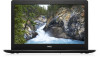
Route the display cable through the routing clips [1].
 |
View all Dell Vostro 3582 manuals
Add to My Manuals
Save this manual to your list of manuals |
Page 54 highlights
4. Replace the five screws (M2.5x5) that secure the left and right hinges to the system board and palm rest and keyboard assembly. 5. Route the display cable through the routing clips [1]. 54 Removing and installing components
-
 1
1 -
2
-
3
-
4
-
5
-
6
-
7
-
8
-
9
-
10
-
11
-
12
-
13
-
14
-
15
-
16
-
17
-
18
-
19
-
20
-
21
-
22
-
23
-
24
-
25
-
26
-
27
-
28
-
29
-
30
-
31
-
32
-
33
-
34
-
35
-
36
-
37
-
38
-
39
-
40
-
41
-
42
-
43
-
44
-
45
-
46
-
47
-
48
-
 49
49 -
 50
50 -
 51
51 -
 52
52 -
 53
53 -
 54
54 -
 55
55 -
 56
56 -
 57
57 -
 58
58 -
 59
59 -
60
-
61
-
62
-
63
-
64
-
65
-
66
-
67
-
68
-
69
-
70
-
71
-
72
-
73
-
74
-
75
-
76
-
77
-
78
-
79
-
80
-
81
-
82
-
83
-
84
-
85
-
86
 |
 |

4.
Replace the five screws (M2.5x5) that secure the left and right hinges to the system board and palm rest and keyboard assembly.
5.
Route the display cable through the routing clips [1].
54
Removing and installing components