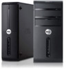
Dell Vostro 470 Owner's Manual
Dell Vostro 470 Manual
 |
View all Dell Vostro 470 manuals
Add to My Manuals
Save this manual to your list of manuals |
Dell Vostro 470 manual content summary:
- Dell Vostro 470 | Owner's Manual - Page 1
Dell Vostro 470 Owner's Manual Regulatory Model: D10M Regulatory Type: D10M002 - Dell Vostro 470 | Owner's Manual - Page 2
better use of your computer. CAUTION: A CAUTION indicates potential damage to hardware or loss of data if instructions are not followed. WARNING Dell™, the DELL logo, Dell Precision™, Precision ON™,ExpressCharge™, Latitude™, Latitude ON™, OptiPlex™, Vostro™, and Wi-Fi Catcher™ are trademarks of Dell - Dell Vostro 470 | Owner's Manual - Page 3
Computer...6 After Working Inside Your Computer...6 2 Removing The Cover...7 Installing The Cover...8 3 Removing The Memory...9 Installing The Memory...9 4 Removing The Expansion Card 11 Installing The Expansion Card Processor...27 Installing The Processor...27 12 Removing The Power Supply Unit 29 - Dell Vostro 470 | Owner's Manual - Page 4
Power Supply Unit...32 13 Removing The System Board 33 Installing The System Board...35 14 Removing The Front Bezel...37 Installing The Front Bezel...38 15 Removing The WLAN Card...39 Installing The WLAN Card...40 16 Removing The Power Switch And The Hard Drive Activity LED 41 Installing The Power - Dell Vostro 470 | Owner's Manual - Page 5
only perform troubleshooting and simple repairs as authorized in your product documentation, or as directed by the online or telephone service and support team. Damage due to servicing that is not authorized by Dell is not covered by your warranty. Read and follow the safety instructions that came - Dell Vostro 470 | Owner's Manual - Page 6
hold the power button for about 4 seconds to turn them off. After Working Inside Your Computer After you complete any replacement procedure, ensure you connect any external devices, cards, and cables before turning on your computer. 1. Replace the cover. CAUTION: To connect a network cable, first - Dell Vostro 470 | Owner's Manual - Page 7
1. Follow the procedures in Before working Inside your computer. 2. Remove the two thumbscrews securing the computer cover to the computer. Figure 1. 3. Slide the computer cover towards the back of the computer, and then remove it from the computer. Figure 2. 4. Lift the computer cover away from the - Dell Vostro 470 | Owner's Manual - Page 8
Figure 3. Installing The Cover 1. Place the computer cover on the computer and slide it inwards from the back of the computer. 2. Replace and tighten the thumbscrews that secure the computer cover on the computer. 3. Follow the procedures in After Working Inside Your Computer. 8 - Dell Vostro 470 | Owner's Manual - Page 9
in Before Working Inside Your Computer. 2. Remove the cover. 3. Press down on the memory retaining tabs on each side of the memory modules and lift the memory module upwards to remove it from the computer. Figure 4. Installing The Memory 1. Align the notch on the memory-card with the tab in the - Dell Vostro 470 | Owner's Manual - Page 10
10 - Dell Vostro 470 | Owner's Manual - Page 11
4 Removing The Expansion Card 1. Follow the procedures in Before Working Inside Your Computer. 2. Remove the cover. 3. Press down on the blue retainer tab in an outward direction and push the retention panel downwards. Figure 5. 4. Press down the latch and pull the expansion card away from the - Dell Vostro 470 | Owner's Manual - Page 12
Installing The Expansion Card 1. Push the expansion card into the card slot and secure the latch. 2. Install the expansion card retainer module to the chassis. 3. Install the cover. 4. Follow the procedures in After Working Inside Your Computer. 12 - Dell Vostro 470 | Owner's Manual - Page 13
5 Removing The Optical Disk Drive 1. Follow the procedures in Before Working Inside Your Computer. 2. Remove the cover. 3. Disconnect the power cable and the data cable from the back of the optical drive. Figure 7. 4. Remove the screws that secure the optical drive to the drive cage. - Dell Vostro 470 | Owner's Manual - Page 14
Figure 9. Installing The Optical Disk Drive 1. Slide the optical drive in through the front of the computer. 2. Replace the screws that secure the optical drive to the drive cage. 3. Connect the power cable and data cable to the optical drive. 4. Install the cover. 5. Follow the procedures in After - Dell Vostro 470 | Owner's Manual - Page 15
6 Removing The Hard Disk Drive 1. Follow the procedures in Before Working Inside Your Computer. 2. Remove the cover. 3. Disconnect the power cable and the data cable from the back of the hard drive. Figure 10. 4. Remove the screws that secure the hard drive cage to the chassis. Figure 11. 15 - Dell Vostro 470 | Owner's Manual - Page 16
. Figure 14. Installing The Hard Disk Drive 1. Tighten the screws that secure the hard drive to the drive cage. 2. Place the hard drive into the slot and tighten the screws that secure the hard drive cage to the chassis. 16 - Dell Vostro 470 | Owner's Manual - Page 17
3. Connect the power cable and data cable to the hard drive. 4. Install the cover. 5. Follow the procedures in After Working Inside Your Computer. 17 - Dell Vostro 470 | Owner's Manual - Page 18
18 - Dell Vostro 470 | Owner's Manual - Page 19
the procedures in Before Working Inside Your Computer. 2. Remove the cover. 3. Disconnect the memory card cable from the system board. Figure 15. 4. Unroute the memory card reader cable from the retention clip. Figure 16. 5. Remove the screws that secure the memory card reader to the drive cage. 19 - Dell Vostro 470 | Owner's Manual - Page 20
the front of the computer. Figure 18. Installing The Memory Card Reader 1. Slide the memory card-reader in through the front of the computer. 2. Replace and tighten the screws that secure the multimedia card-reader to the drive cage. 3. Route the memory card reader cable through the retention - Dell Vostro 470 | Owner's Manual - Page 21
8 Removing The Rear System Fan 1. Follow the procedures in Before Working Inside Your Computer. 2. Remove the cover. 3. Disconnect the fan cable from the system board. Figure 19. 4. Remove the screws that secure the fan to the chassis and lift the fan out of the computer. Figure 20. 21 - Dell Vostro 470 | Owner's Manual - Page 22
Installing The Rear System Fan 1. Place the fan towards the center of the computer into the chassis. 2. While holding the chassis fan in place, replace the screws that secure the fan to the chassis. 3. Reconnect the fan cable to the system board. 4. Install the cover. 5. Follow the procedures in - Dell Vostro 470 | Owner's Manual - Page 23
1. Follow the procedures in Before Working Inside Your Computer. 2. Remove the cover. 3. Remove the expansion card. 4. Press the release latch away from the battery coin-cell battery into the slot. 2. Install the expansion card. 3. Install the cover. 4. Follow the procedures in After Working - Dell Vostro 470 | Owner's Manual - Page 24
24 - Dell Vostro 470 | Owner's Manual - Page 25
Removing The Heat Sink 1. Follow the procedures in Before Working Inside Your Computer. 2. Remove the cover. 3. Disconnect the heat sink fan cable from the system board. 10 Figure 22. 4. Remove the screws that secure the heat sink assembly - Dell Vostro 470 | Owner's Manual - Page 26
Installing The Heat Sink 1. Connect the heat sink fan cable to the system board. 2. Install the screws that secure the heat sink assembly to the system board. 3. Install the cover. 4. Follow the procedures in After Working Inside Your Computer. 26 - Dell Vostro 470 | Owner's Manual - Page 27
to release it from the retention hook that secures it. 5. Raise the processor cover and lift up the processor to remove it from the computer. Figure 24. Installing The Processor 1. Install the processor into the socket. 2. Press down the processor cover to secure it inside the socket. 3. Push the - Dell Vostro 470 | Owner's Manual - Page 28
28 - Dell Vostro 470 | Owner's Manual - Page 29
Unit 1. Follow the procedures in Before Working Inside Your Computer. 2. Remove the cover. 3. Press the release latch and lift up the cable holder to disconnect it from the latch on the system board. Figure 25. 4. Disconnect the power supply cable from the back of the hard drive. Figure 26. 29 - Dell Vostro 470 | Owner's Manual - Page 30
5. Disconnect the power supply cable from the back of the optical drive. Figure 27. 6. Disconnect the power supply cable from the system board. Figure 28. 7. Remove the screws that secure the power supply unit to the computer chassis. 30 - Dell Vostro 470 | Owner's Manual - Page 31
Figure 29. 8. Push the blue release tab beside the power supply and slide the power supply unit towards the front of the computer. Figure 30. 9. Lift the power supply unit out of the computer. 31 - Dell Vostro 470 | Owner's Manual - Page 32
31. Installing The Power Supply Unit 1. Install the power supply unit into the computer. 2. Slide the power supply unit towards the back of the computer till it snaps into place. 3. Install the screws that secure the power supply unit to the computer. 4. Connect all the power supply cables to the - Dell Vostro 470 | Owner's Manual - Page 33
procedures in Before Working Inside Your Computer. 2. Remove the cover. 3. Remove the memory modules. 4. Remove the expansion card. 5. Remove the heat sink. 6. Remove the processor. 7. Remove the hard drive. 8. Remove the optical drive. 9. Remove the memory card reader. 10. Disconnect and unthread - Dell Vostro 470 | Owner's Manual - Page 34
Figure 33. 12. Slide the system board towards the front of the computer. Figure 34. 13. Lift the system board out of the computer. 34 - Dell Vostro 470 | Owner's Manual - Page 35
the system board to the computer chassis. 4. Thread and connect all the cables to the system board. 5. Install the processor. 6. Install the heat sink. 7. Install the memory modules. 8. Install the optical drive. 9. Install the hard drive. 10. Install the expansion card. 11. Install the cover. 12 - Dell Vostro 470 | Owner's Manual - Page 36
36 - Dell Vostro 470 | Owner's Manual - Page 37
Removing The Front Bezel 1. Follow the procedures in Before Working Inside Your Computer. 2. Remove the cover. 3. Lift the retention clips slightly upward to release that edge of the bezel from the chassis. 14 Figure 36. 4. Remove the front bezel from the computer. Figure 37. 37 - Dell Vostro 470 | Owner's Manual - Page 38
Installing The Front Bezel 1. Rotate the bezel towards the computer to place the hooks on the chassis. 2. Place the retention clips downwards to lock the edge of the bezel on the chassis. 3. Install the cover. 4. Follow the procedures in After Working Inside Your Computer. 38 - Dell Vostro 470 | Owner's Manual - Page 39
cables from the WLAN card. 5. Remove the screw that secures the WLAN card and remove it from the card slot. 15 Figure 38. 6. Release the WLAN card cable from the routing clips and lift them in an upward direction. Figure 39. 7. Remove the WLAN card cable from the computer by sliding it around - Dell Vostro 470 | Owner's Manual - Page 40
clips. 2. Slide the WLAN card into its slot. 3. Tighten the screws to secure the WLAN card in place. 4. Connect the antenna cables according to the color code on the WLAN card. 5. Install the front bezel. 6. Install the cover. 7. Follow the procedures in After Working Inside Your Computer. 40 - Dell Vostro 470 | Owner's Manual - Page 41
Hard Drive Activity LED 1. Follow the procedures in Before Working Inside Your Computer. 2. Remove the cover. 3. Remove the front bezel. 4. Disconnect the power switch cable from the system board. Figure 41. 5. Unthread the power switch cable from the routing clips. Figure 42. 6. Unthread the hard - Dell Vostro 470 | Owner's Manual - Page 42
Drive Activity LED 1. Thread the power switch cable and the hard drive activity LED cable through the routing clips. 2. Connect the power-button cable to the system board. 3. Insert the power button and hard drive activity LED into the front of the computer. 4. Install the front bezel. 5. Install - Dell Vostro 470 | Owner's Manual - Page 43
6. Follow the procedures in After Working Inside Your Computer. 43 - Dell Vostro 470 | Owner's Manual - Page 44
44 - Dell Vostro 470 | Owner's Manual - Page 45
Removing The Front Audio Module 1. Follow the procedures in Before Working Inside Your Computer. 2. Remove the cover. 3. Remove the front bezel. 4. Disconnect the front audio module cable from the system board. 17 Figure 46. 5. Remove the front audio module - Dell Vostro 470 | Owner's Manual - Page 46
that secures the front audio module to the front bezel and remove the front audio module from the computer. Figure 48. Installing The Front Audio Module 1. Place the front audio module on the front bezel bezel. 5. Install the cover. 6. Follow the procedures in After Working Inside Your Computer. 46 - Dell Vostro 470 | Owner's Manual - Page 47
Removing The Front USB Module 1. Follow the procedures in Before Working Inside Your Computer. 2. Remove the cover. 3. Remove the front bezel. 4. Disconnect the front USB module data cable and the power cable from the system board. 18 Figure 49. 5. Remove the screw that secures the front USB - Dell Vostro 470 | Owner's Manual - Page 48
4. Install the cover. 5. Follow the procedures in After Working Inside Your Computer. 48 - Dell Vostro 470 | Owner's Manual - Page 49
computer. • set or change a user-selectable option such as the user password. • read the current amount of memory you see the Microsoft Windows desktop. Then, shut down your computer and try again. System Setup installed hardware, power view information about your computer conservation, and - Dell Vostro 470 | Owner's Manual - Page 50
Displays the BIOS revision. BIOS Build Date Displays the BIOS build date. System Name Displays the computer model number. System Time Re-sets the time on the computer's internal clock. System Date Re-sets the date on the computer's internal calendar. Service Tag Displays the service tag of - Dell Vostro 470 | Owner's Manual - Page 51
processor L1 cache size. Displays the processor L2 cache size. Displays the processor L3 cache size. Description Displays the total computer memory. Displays the available computer memory. Displays the memory speed. Displays the type and technology. Description Displays the model number and capacity - Dell Vostro 470 | Owner's Manual - Page 52
Option Intel Virtualization Technology CPU XD Support Limit CPUID Value Multi Core Support Intel Turbo Boost Technology AMD Cool 'N' Quiet Secure Virtual Machine Mode Description Enable or disable the Intel Virtualization feature. Default: Enabled Enable or disable the CPU XD feature. Default: - Dell Vostro 470 | Owner's Manual - Page 53
Up by Integrated LAN/WLAN AC Recovery USB PowerShare in S4/S5 State USB PowerShare in Sleep State Auto Power On Auto Power On Mode Auto Power On Date Auto Power On Time Enable or Disable the Wake Up by Integrated LAN/WLAN feature. Default: Disabled Allows the computer to restore the AC Default - Dell Vostro 470 | Owner's Manual - Page 54
54 - Dell Vostro 470 | Owner's Manual - Page 55
have failed The computer failed to complete the boot routine three at checkpoint [nnnn]. For help in resolving this problem, consecutive times for the same error. please note this checkpoint and contact Dell Technical Support. System fan failure Possible fan failure CPU fan failure CPU fan has - Dell Vostro 470 | Owner's Manual - Page 56
For help in resolving this problem, please note this checkpoint and contact Dell Technical Support The computer failed to complete the boot routine three consecutive times for the same error. CMOS checksum error Possible motherboard failure or RTC battery low. CPU fan failure CPU fan has failed - Dell Vostro 470 | Owner's Manual - Page 57
not solve the problem, replace the keyboard No bootable partition on hard disk power source to connect the USB device, or if the device has two USB cables, connect both of them. CAUTION - Hard Drive SELF MONITORING SYSTEM has reported that a parameter has exceeded its normal operating range. Dell - Dell Vostro 470 | Owner's Manual - Page 58
58 - Dell Vostro 470 | Owner's Manual - Page 59
configuration of your computer, click Start → Help and Support and select the option to view information about your computer. Table 10. System Information System Information Model Vostro 470 Processor Intel Core i3 (2nd Generation) Intel Core i5 (3rd Generation) Intel Core i7 (3rd Generation - Dell Vostro 470 | Owner's Manual - Page 60
supported by your computer may vary depending on the configuration ordered. 2 GB, 4 GB, 8 GB, 12 GB, and 16 GB. 2 GB 32 GB NA Intel HD Graphics 2500/4000 one PCI Express x16, single-width, full length graphics card. upto 1024 MB upto 2 GB discrete video memory NOTE: The available video memory - Dell Vostro 470 | Owner's Manual - Page 61
Audio Audio Type Controller Table 17. Drives Drives Externally accessible Internally accessible Table 18. Expansion Bus Expansion Bus PCI Express x1 Connectors Connector size PCI Express x16 Connectors Connector size PCI-E mini-card Connectors Connector size Table 19. Power Power Input voltage Input - Dell Vostro 470 | Owner's Manual - Page 62
Table 20. Environmental Environmental Temperature: Operating Storage Relative humidity: Maximum vibration: Operating Non-Operating Maximum shock: Operating Non-Operating Altitude: Operating Storage Airborne contaminant level 10 °C to 35 °C (50 °F to 95 °F) -10 °C to 45 °C (-14 °F to 113 °F) 20 % to - Dell Vostro 470 | Owner's Manual - Page 63
may not be available in your area. To contact Dell for sales, technical support, or customer service issues: 1. Visit support.dell.com. 2. Select your support category. 3. If you are not a U.S. customer, select your country code at the bottom of the support.dell.com page, or select All to see more
-
 1
1 -
 2
2 -
 3
3 -
 4
4 -
 5
5 -
 6
6 -
 7
7 -
8
-
9
-
10
-
11
-
12
-
13
-
14
-
15
-
16
-
17
-
18
-
19
-
20
-
21
-
22
-
23
-
24
-
25
-
26
-
27
-
28
-
29
-
30
-
31
-
32
-
33
-
34
-
35
-
36
-
37
-
38
-
39
-
40
-
41
-
42
-
43
-
44
-
45
-
46
-
47
-
48
-
49
-
50
-
51
-
52
-
53
-
54
-
55
-
56
-
57
-
58
-
59
-
60
-
61
-
62
-
63
 |
 |

Dell Vostro 470
Owner's Manual
Regulatory Model: D10M
Regulatory Type: D10M002