Dell Vostro 7500 Service Manual
Dell Vostro 7500 Manual
 |
View all Dell Vostro 7500 manuals
Add to My Manuals
Save this manual to your list of manuals |
Dell Vostro 7500 manual content summary:
- Dell Vostro 7500 | Service Manual - Page 1
Vostro 7500 Service Manual Regulatory Model: P102F Regulatory Type: P102F003 - Dell Vostro 7500 | Service Manual - Page 2
of data and tells you how to avoid the problem. WARNING: A WARNING indicates a potential for property damage, personal injury, or death. © 2020 Dell Inc. or its subsidiaries. All rights reserved. Dell, EMC, and other trademarks are trademarks of Dell Inc. or its subsidiaries. Other trademarks may be - Dell Vostro 7500 | Service Manual - Page 3
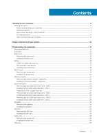
instructions...6 Before working inside your computer...6 Safety precautions...7 Electrostatic discharge-ESD protection...7 ESD field service Battery...16 Lithium-ion battery precautions...16 Removing the 6-cell battery...17 Installing the 6-cell battery the SSD-1 support bracket...24 Removing - Dell Vostro 7500 | Service Manual - Page 4
coin-cell battery...40 I/O board...41 Removing the I/O board...41 Installing the I/O board...42 Power button with fingerprint reader (optional)...44 Removing the power button and optional fingerprint reader 44 Installing the power button with optional fingerprint reader 45 DC-in port...47 Removing - Dell Vostro 7500 | Service Manual - Page 5
...76 Updating BIOS on systems with BitLocker enabled 76 Updating the Dell BIOS in Linux and Ubuntu environments 76 Flashing the BIOS from setup password...81 Deleting or changing an existing system setup password 82 6 Troubleshooting...83 Built-in self-test (BIST)...83 System board built-in self - Dell Vostro 7500 | Service Manual - Page 6
only perform troubleshooting and simple repairs as authorized in your product documentation, or as directed by the online or telephone service and support team. Damage due to servicing that is not authorized by Dell is not covered by your warranty. Read and follow the safety instructions that came - Dell Vostro 7500 | Service Manual - Page 7
instructions Dell products with standby power must be unplugged before you open the case Remove the battery from tablets. the use of a field service electrostatic discharge (ESD) kit. as intermittent problems or a shortened product life span. damage to recognize and troubleshoot is the intermittent ( - Dell Vostro 7500 | Service Manual - Page 8
sink casings, away from internal parts that are insulators and often highly charged. • Working Environment - Before deploying the ESD Field Service kit servicing Dell products. In addition, it is critical that technicians keep sensitive parts separate from all insulator parts while performing service - Dell Vostro 7500 | Service Manual - Page 9
Steps 1. Connect any telephone or network cables to your computer. CAUTION: To connect a network cable, first plug the cable into the network device and then plug it into the computer. 2. Connect your computer and all attached devices to their electrical outlets. 3. Turn on your computer. 4. If - Dell Vostro 7500 | Service Manual - Page 10
components of your system 1. Base cover 2. Battery 3. System fan 4. Heat sink 5. Memory module 6. DC-in port 7. Speaker 8. System board 9. Touchpad 10. Palm-rest and keyboard assembly 11. Display assembly 12. Power button with fingerprint reader 13. Coin-cell battery 14. I/O board 15. GPU fan 16 - Dell Vostro 7500 | Service Manual - Page 11
18. Solid-state drive shield NOTE: Dell provides a list of components and their part numbers for the original system configuration purchased. These parts are available according to warranty coverages purchased by the customer. Contact your Dell sales representative for purchase options. Major - Dell Vostro 7500 | Service Manual - Page 12
with the configuration ordered. Table 1. Screw list Component Base cover Screw type M2x4 M2x7.5 - captive Quantity 7 2 Screw image Six-cell battery M2x5 8 WLAN M2x3 1 Solid-state drive - 1 M2x3 1 Solid-state drive - 2 M2x3 1 GPU fan M2x4 2 System fan M2x4 2 Heat sink - UMA - Dell Vostro 7500 | Service Manual - Page 13
Hinge screws Screw type M2.5x5 M2.5x4 Quantity 2 2 Screw image I/O board M2x3 1 Power button with fingerprint M1.6x2.5 2 reader DC-in port M2x3 1 Touchpad M2x2 3 M1.6x2 2 Display assembly M2.5x5 2 M2.5x4 2 System board M2x3 4 Base cover Removing the base cover Prerequisites - Dell Vostro 7500 | Service Manual - Page 14
14 Disassembly and reassembly - Dell Vostro 7500 | Service Manual - Page 15
base cover starting from the recess at the hinge area and work your way around. 4. Lift the base cover off away from the laptop. Installing the base cover Prerequisites If you are replacing a component, remove the existing component before performing the installation procedure. About this task The - Dell Vostro 7500 | Service Manual - Page 16
and keyboard assembly. Next steps Follow the procedure in after working inside your computer. Battery Lithium-ion battery precautions CAUTION: • Exercise caution when handling Lithium-ion batteries. • Discharge the battery as much as possible before removing it from the system. This can be done by - Dell Vostro 7500 | Service Manual - Page 17
purchase genuine batteries from www.dell.com or authorized Dell partners and resellers. Removing the 6-cell battery Prerequisites 1. Follow the procedure in before working inside your computer. 2. Remove the base cover. About this task NOTE: Vostro 7500 comes with standard 3-cell battery. The figure - Dell Vostro 7500 | Service Manual - Page 18
component, remove the existing component before performing the installation procedure. About this task NOTE: Vostro 7500 comes with standard 3-cell battery. The figure indicates the location of the 6-cell battery and provides a visual representation of the installation procedure. Steps 1. Place the - Dell Vostro 7500 | Service Manual - Page 19
. WLAN card Removing the WLAN card Prerequisites 1. Follow the procedure in before working inside your computer. 2. Remove the base cover. 3. Remove the battery. About this task The figure indicates the location of the WLAN card and provides a visual representation of the removal procedure. Steps - Dell Vostro 7500 | Service Manual - Page 20
card bracket on the WLAN card. 4. Replace the single screw (M2x3) to secure the WLAN card bracket to the WLAN card. Next steps 1. Install the battery. 2. Install the base cover. 20 Disassembly and reassembly - Dell Vostro 7500 | Service Manual - Page 21
memory module - single slot Prerequisites 1. Follow the procedure in before working inside your computer. 2. Remove the base cover. 3. Disconnect the battery. About this task The figure indicates the location of the memory module and provides a visual representation of the removal procedure. Steps - Dell Vostro 7500 | Service Manual - Page 22
2. Use your fingertips to carefully spread apart the securing-clips on each end of the memory-module slot until the memory module pops up. 3. Slide and remove the memory module off the memory module slot on the system board. Installing the memory module - single slot Prerequisites If you are - Dell Vostro 7500 | Service Manual - Page 23
2280 solid-state drive - SSD-1 Prerequisites 1. Follow the procedure in before working inside your computer. 2. Remove the base cover. 3. Disconnect the battery . About this task The figure indicates the location of the solid-state drive and provides a visual representation of the removal procedure - Dell Vostro 7500 | Service Manual - Page 24
. 3. Follow the procedure in after working inside your computer. Replacing the SSD-1 support bracket Prerequisites 1. Follow the procedure in before working inside your computer. 2. Remove the base cover. 3. Remove the battery. 4. Remove the M.2 2280 SSD or M.2 2230 SSD. About this task The figure - Dell Vostro 7500 | Service Manual - Page 25
solid-state drive - SSD-1 Prerequisites 1. Follow the procedure in before working inside your computer. 2. Remove the base cover. 3. Disconnect the battery. NOTE: Slot 1 supports both M.2 2280 and M.2 2230 solid-state drives. About this task The figure indicates the location of the solid-state drive - Dell Vostro 7500 | Service Manual - Page 26
solid-state drive - SSD-1 Prerequisites If you are replacing a component, remove the existing component before performing the installation procedure. NOTE: Slot 1 supports both M.2 2230 and M.2 2280 SSD. About this task The figure indicates the location of the solid-state drive bracket and provides - Dell Vostro 7500 | Service Manual - Page 27
2280 solid-state drive - SSD-2 Prerequisites 1. Follow the procedure in before working inside your computer. 2. Remove the base cover. 3. Disconnect the battery. About this task The figure indicates the location of the solid-state drive and provides a visual representation of the removal procedure - Dell Vostro 7500 | Service Manual - Page 28
solid-state drive - SSD-2 Prerequisites If you are replacing a component, remove the existing component before performing the installation procedure. NOTE: Slot 2 supports both M.2 2230 and M.2 2280 SSD. About this task The figure indicates the location of the solid-state drive bracket and provides - Dell Vostro 7500 | Service Manual - Page 29
the single (M2x3) screw to secure the solid-state drive module to the palm-rest and keyboard assembly. Next steps 1. Connect the battery. 2. Install the base cover. 3. Follow the procedure in after working inside your computer. Speakers Removing the speakers Prerequisites 1. Follow the procedure in - Dell Vostro 7500 | Service Manual - Page 30
Steps 1. Disconnect the speaker cable from the system board. 2. Note the routing of the speaker cable, and remove the speaker cable from the routing guides on the palm-rest and keyboard assembly. NOTE: Note the position of the rubber grommets before lifting the speakers. 3. Lift the speakers, along - Dell Vostro 7500 | Service Manual - Page 31
alignment posts and rubber grommets, place the speakers in the slots on the palm-rest and keyboard assembly. 2. Route the speaker cable through the routing guides on the palm-rest and keyboard assembly. 3. Connect the speaker cable to the system board. Next steps 1. Install the WLAN. 2. Install the - Dell Vostro 7500 | Service Manual - Page 32
GPU fan Removing the GPU fan Prerequisites 1. Follow the procedure in before working inside your computer. 2. Remove the base cover. 3. Remove the battery. About this task The figure indicates the location of the GPU fan and provides a visual representation of the removal procedure. Steps 1. Flip - Dell Vostro 7500 | Service Manual - Page 33
to secure the GPU fan to the palm-rest and keyboard assembly. 4. Connect the GPU fan cable to the system board. Next steps 1. Install the battery. 2. Install the base cover. 3. Follow the procedure in after working inside your computer. Disassembly and reassembly 33 - Dell Vostro 7500 | Service Manual - Page 34
System fan Removing the system fan Prerequisites 1. Follow the procedure in before working inside your computer. 2. Remove the base cover. 3. Remove the battery. About this task The figure indicates the location of the system fan and provides a visual representation of the removal procedure. Steps - Dell Vostro 7500 | Service Manual - Page 35
the system fan to the palm-rest and keyboard assembly. 4. Connect the system fan cable to the system board. Next steps 1. Install the battery. 2. Install the base cover. 3. Follow the procedure in after working inside your computer. Heat sink Removing the heat sink - UMA Prerequisites NOTE: The - Dell Vostro 7500 | Service Manual - Page 36
Steps 1. Flip the mylar cover open. 2. In sequential order (as indicated on the heat sink), loosen the four captive screws that secure the heat sink to the system board. 3. Lift and remove the heat sink off the palm-rest and keyboard assembly. Installing the heat sink - UMA Prerequisites If you are - Dell Vostro 7500 | Service Manual - Page 37
tighten the four captive screws that secure the heat sink to the system board. 3. Replace the mylar cover back. Next steps 1. Install the battery. 2. Install the base cover. 3. Follow the procedure in after working inside your computer. Removing the heat sink - discrete Prerequisites NOTE: The heat - Dell Vostro 7500 | Service Manual - Page 38
About this task The figure indicates the location of the heat sink and provides a visual representation of the removal procedure. Steps 1. Flip the mylar cover open. 2. In sequential order (as indicated on the heat sink), loosen the seven captive screws that secure the heat sink to the system board - Dell Vostro 7500 | Service Manual - Page 39
the heat sink to the system board in sequential order (as indicated on the heat sink). 3. Replace the mylar cover back. Next steps 1. Install the battery. 2. Install the base cover. 3. Follow the procedure in after working inside your computer. Coin-cell - Dell Vostro 7500 | Service Manual - Page 40
resets the BIOS setup program settings to default. It is recommended that you note the BIOS setup program settings before removing the coin-cell battery. The system does not boot to the operating system if settings are not saved. About this task The figure indicates the location of the coin- - Dell Vostro 7500 | Service Manual - Page 41
1. Follow the procedure in before working inside your computer. 2. Remove the base cover. 3. Remove the battery. 4. Remove the GPU fan. About this task NOTE: Removing the I/O board disconnects the battery from the system board. The figure indicates the location of the I/O board and provides a visual - Dell Vostro 7500 | Service Manual - Page 42
the I/O-board cable from the I/O board. 4. Open the latch, and disconnect the USH cable (optional) from the I/O board. 5. Disconnect the coin-cell battery cable from the I/O board. 6. Remove the single screw (M2x3) that secures the I/O board to the palm-rest and keyboard assembly. 7. Lift the - Dell Vostro 7500 | Service Manual - Page 43
. 4. Connect the USH cable (optional) to the I/O board and close the latch to secure the cable. 5. Connect the coin-cell battery cable to the I/O board and adhere the coin-cell battery. 6. Connect the I/O-board cable to the I/O board and close the latch to secure the cable. 7. Lower the left-display - Dell Vostro 7500 | Service Manual - Page 44
button and optional fingerprint reader Prerequisites 1. Follow the procedure in before working inside your computer. 2. Remove the base cover. 3. Remove the battery. 4. Remove the GPU fan. 5. Remove the I/O board. About this task The figure indicates the location of the power button with optional - Dell Vostro 7500 | Service Manual - Page 45
Steps 1. Remove the transparent adhesive cover over the fingerprint reader. 2. Lift the latch, and unplug the USH (optional) cable from the connector on the palm-rest assembly. NOTE: Remove the USH (optional) cable and keep it aside as it is already disconnected from the other end. 3. Unplug the - Dell Vostro 7500 | Service Manual - Page 46
and keyboard assembly and close the latch. 6. Replace the transparent adhesive cover back. Next steps 1. Install the I/O board. 2. Install the GPU fan. 3. Install the battery. 4. Install the base cover. 5. Follow the procedure in after working inside your computer. 46 Disassembly and reassembly - Dell Vostro 7500 | Service Manual - Page 47
1. Follow the procedure in before working inside your computer. 2. Remove the base cover. 3. Remove the battery. About this task The figure indicates the location of the DC-in port and provides a visual representation of the removal procedure. Steps 1. Remove the two screws (M2.5x5) and - Dell Vostro 7500 | Service Manual - Page 48
on the palm-rest and keyboard assembly. 2. Replace the single screw (M2x3) that secures the DC-in port to the palm-rest and keyboard assembly. 3. Connect the DC-in port cable to the system board. 4. Using the alignment posts, close the left display hinge. 5. Replace the two screws (M2.5x5) and (M2 - Dell Vostro 7500 | Service Manual - Page 49
. Touchpad Removing the touchpad Prerequisites 1. Follow the procedure in before working inside your computer. 2. Remove the base cover. 3. Remove the battery. 4. Remove the WLAN. About this task The figure indicates the location of the touchpad and provides a visual representation of the removal - Dell Vostro 7500 | Service Manual - Page 50
Steps 1. Unplug the speaker cable from its connector on the system board. 2. Peel the adhesive tape, and unroute the speaker cable. 3. Remove the three (M2x2) screws that secure the touchpad bracket to the palm-rest and keyboard assembly. 4. Lift the touchpad bracket off the palm-rest and keyboard - Dell Vostro 7500 | Service Manual - Page 51
cable, and replace the adhesive tape. 9. Plug the speaker cable to its connector. Next steps 1. Install the WLAN. 2. Install the battery. 3. Install the base cover. 4. Follow the procedure in after working inside your computer. Display assembly Removing the display assembly Prerequisites 1. Follow - Dell Vostro 7500 | Service Manual - Page 52
52 Disassembly and reassembly - Dell Vostro 7500 | Service Manual - Page 53
Steps 1. Locate the display cable and display hinges on your computer. 2. Peel the tape that secures the display cable to the system board. 3. Open the latch, and disconnect the display cable from the system board. 4. Remove the two screws (M2.5x5) and (M2.5x4) that secure the left-display hinge to - Dell Vostro 7500 | Service Manual - Page 54
Installing the display assembly Prerequisites If you are replacing a component, remove the existing component before performing the installation procedure. About this task The figure indicates the location of the component and provides a visual representation of the installation procedure. 54 - Dell Vostro 7500 | Service Manual - Page 55
board. 6. Connect the display cable on to the connector on the system board and adhere the tape to the system board. Next steps 1. Install the battery. 2. Install the base cover. 3. Follow the procedure in after working inside your computer. Disassembly and reassembly 55 - Dell Vostro 7500 | Service Manual - Page 56
System board Removing the system board Prerequisites 1. Follow the procedure in before working inside your computer. 2. Remove the base cover. 3. Remove the battery. 4. Remove the WLAN card. 5. Remove the SSD-1 (M.2 2280 or M.2 2230). 6. Remove the SSD-2 (M.2 2280 or M.2 2230). 7. Remove the GPU fan - Dell Vostro 7500 | Service Manual - Page 57
the display cable to the system board. 3. Open the latch, and disconnect the display cable from the system board. 4. Remove and lift the USB Type-C port off the system board. 5. Open the latch, and disconnect the I/O cable from the system board. 6. Disconnect the speaker cable from the system board - Dell Vostro 7500 | Service Manual - Page 58
About this task The figure indicates the location of the system board and provides a visual representation of the installation procedure. 58 Disassembly and reassembly - Dell Vostro 7500 | Service Manual - Page 59
Align and place the USB Type-C port bracket. 4. Replace the two screws (M2x3) that secure the USB Type-C port bracket to the system board. 5. Connect ). 7. Install the SSD-2 (M.2 2280 or M.2 2230). 8. Install the battery. 9. Install the base cover. 10. Follow the procedure in after working inside - Dell Vostro 7500 | Service Manual - Page 60
before working inside your computer. 2. Remove the base cover. 3. Remove the battery. 4. Remove the WLAN card. 5. Remove the SSD-1 (M.2 2280 or discrete or UMA based on the configuration selected. 12. Remove the DC-in port. 13. Remove the power button with fingerprint reader. 14. Remove the memory - Dell Vostro 7500 | Service Manual - Page 61
the system board. 2. Install the touchpad. 3. Install the DC-in port. 4. Install the power button with fingerprint reader. 5. Install the I/O the display assembly. 8. Install the memory module. 9. Install the coin-cell battery. 10. Install the heat sink - discrete or UMA based on the configuration - Dell Vostro 7500 | Service Manual - Page 62
This chapter details the supported operating systems along with instructions on how to install the drivers. Topics: • Downloading Windows drivers Downloading Windows drivers Steps 1. Turn on the notebook. 2. Go to Dell.com/support. 3. Click Product Support, enter the Service Tag of your notebook - Dell Vostro 7500 | Service Manual - Page 63
about the hardware installed in your computer, such as the amount of RAM and the size of the hard drive. • Change the system configuration the BIOS in Windows • System and setup password Boot menu Press when the Dell logo appears to initiate a one-time boot menu with a list of the valid - Dell Vostro 7500 | Service Manual - Page 64
or hard drive). During the Power-on Self-Test (POST), when the Dell logo appears, you can: • Access System Setup by pressing F2 key Service Tag • Asset Tag • Manufacture Date • Ownership Date • Express Service Code • Ownership Tag • Signed Firmware Update • Battery • Primary • Battery Level • Battery - Dell Vostro 7500 | Service Manual - Page 65
the computer attempts to find an operating system. The options are: • Windows Boot Manager • UEFI Hard Drive NOTE: Legacy Boot mode is not supported on this platform. Secure Boot helps ensure your system boots using only validated boot software. Enable Secure Boot-By default, this option is disabled - Dell Vostro 7500 | Service Manual - Page 66
• Enable Internal Speaker Allows you to enable or disable the internal/integrated USB configuration. The options are: • Enable USB Boot Support • Enable External USB Port By default, all the options are enabled. Allows you to enable or disable the Fingerprint Reader Device. Enable Fingerprint Reader - Dell Vostro 7500 | Service Manual - Page 67
By default, the RAID On option is enabled. NOTE: SATA is configured to support RAID mode. Allows you to enable or disable various drives on board. The By default, this option is enabled. EcoPower increases the battery life by reducing the display brightness when appropriate. Displays full screen - Dell Vostro 7500 | Service Manual - Page 68
Work Period is disabled. Use ExpressCharge for accelerated battery charging. Peak Shift Allows the system to run on battery during peak power usage hours. Peak Shift - • Cool • Quiet • Ultra Performance USB Wake Support Enable USB Wake Allows you to enable USB devices to wake the system - Dell Vostro 7500 | Service Manual - Page 69
Dell USB-C Dock is enabled. NOTE: These features are only functional when the AC power adapter is connected. If the AC power adapter is removed before Standby, the BIOS removes power from all USB ports to conserve battery disable the Intel Speed Shift Technology support. By default,Intel Speed Shift - Dell Vostro 7500 | Service Manual - Page 70
the BIOS module interface of the optional Absolute Persistence Module service from Absolute Software. The options are: • Enable Absolute-This password. Upper Case Letter When enabled, this field reinforces password must contain at least one upper capital letter. Lower Case Letter When enabled, - Dell Vostro 7500 | Service Manual - Page 71
in Locked mode. Master Password Lockout Allows you to disable master password support. Enable Master Password Lockout - By default, this option is disabled. Allows you to recover cloud service operating system if the main operating system and/or local service operating system fails to boot with - Dell Vostro 7500 | Service Manual - Page 72
control the automatic flow for SupportAssist System Resolution Console and for Dell OS Recovery Tool. The options are: • Off •1 • 2 - Default •3 System management Table 12. System management Option Service Tag Description Displays the service tag of your computer. Asset Tag An Asset Tag is - Dell Vostro 7500 | Service Manual - Page 73
system has AC adapter plugged in. This feature defines the timeout value for the keyboard backlight when the system is running only on battery power. The options are: • 5 seconds • 10 seconds - This option is enabled by default. • 15 seconds • 30 seconds • 1 minute • 5 minutes • 15 minutes • Never - Dell Vostro 7500 | Service Manual - Page 74
protocols are installed and available. Enable UEFI Network Stack - This option is enabled by default. Performance Table 16. Performance Option Multi Core Support Description This field specifies whether the process has one or all cores enabled. The default value is set to the maximum number of - Dell Vostro 7500 | Service Manual - Page 75
Option Intel SpeedStep C-States Control Intel Turbo Boost Technology Intel Hyper-Threading Technology Description • All Cores - This option is enabled by default. •1 •2 •3 This feature allows the system to dynamically adjust processor voltage and core frequency, decreasing average power consumption - Dell Vostro 7500 | Service Manual - Page 76
system board or if an update is available. For laptops, ensure that your computer battery is fully charged and connected to a power before initiating Go to Dell.com/support. • Enter the Service Tag or Express Service Code and click Submit. • Click Detect Product and follow the instructions on screen - Dell Vostro 7500 | Service Manual - Page 77
from the Dell Support website and copied to the root of the USB key. • AC power adapter that is connected to the system. • Functional system battery to flash power off state, insert the USB key where you copied the flash into a USB port of the system . 2. Power on the system and press the F12 key to - Dell Vostro 7500 | Service Manual - Page 78
5. Select external USB device. 78 System setup - Dell Vostro 7500 | Service Manual - Page 79
6. Once the file is selected, double-click the flash target file and click Submit. 7. Click Update BIOS for the system to reboot and flash the BIOS. System setup 79 - Dell Vostro 7500 | Service Manual - Page 80
A Flash BIOS window opens prompting whether you want to confirm the update. 8. Click Confirm Update BIOS. 80 System setup - Dell Vostro 7500 | Service Manual - Page 81
Once complete, the system reboots and the BIOS update process is completed. System and setup password Table 18. System and setup password Password type System password Setup password Description Password that you must enter to log on to your system. Password that you must enter to access and make - Dell Vostro 7500 | Service Manual - Page 82
assign the system password: • A password can have up to 32 characters. • The password can contain the numbers 0 through 9. • Only lower case letters are valid, upper case letters are not allowed. • Only the following special characters are allowed: space 3. Type the system password that you entered - Dell Vostro 7500 | Service Manual - Page 83
when there is a system board failure. 3. Replace the system board to fix the issue. NOTE: The battery status LED does not illuminate if the system board is functioning properly. If further troubleshooting is required, proceed with the applicable Guided Resolution for No Power/No POST, and so on - Dell Vostro 7500 | Service Manual - Page 84
LCD by performing an LCD Power Rail test. If there is no power going to the LCD, the battery status LED flashes a [2,8] LED error code. Display panel power rail built-in self-test (L-BIST) About is no power going to the LCD, the battery status LED flashes a [2,8] LED error code. 84 Troubleshooting - Dell Vostro 7500 | Service Manual - Page 85
BIST outcome Off Solid amber M-BIST No fault detected with system board. Indicates a problem with the system board. SupportAssist diagnostics About this task The SupportAssist diagnostics (previously known allowing you to: • Run tests automatically or in an interactive mode Troubleshooting 85 - Dell Vostro 7500 | Service Manual - Page 86
computer boots, press the F12 key as the Dell logo appears. 3. On the boot menu screen, RAM is detected. The following table shows different power and battery-status light patterns and associated problems. Table 21. LED codes Diagnostic light codes 1,1 1,2 1,3 1,4 1, 5 1, 6 1, 7 1, 8 1, 9 Problem - Dell Vostro 7500 | Service Manual - Page 87
website to troubleshoot and fix your computer when it fails to boot into their primary operating system due to software or hardware failures. For more information about the Dell SupportAssist OS Recovery, see Dell SupportAssist OS Recovery User's Guide at www.dell.com/ support. Flashing the BIOS - Dell Vostro 7500 | Service Manual - Page 88
Service Tag, use the Autodefect feature or manually SLN143196 at www.dell.com/support. 3. Copy the instructions on the screen to complete the BIOS update. Backup media and recovery options It is recommended to create a recovery drive to troubleshoot and fix problems that may occur with Windows. Dell - Dell Vostro 7500 | Service Manual - Page 89
. Availability varies by country and product, and some services may not be available in your area. To contact Dell for sales, technical support, or customer service issues: Steps 1. Go to Dell.com/support. 2. Select your support category. 3. Verify your country or region in the Choose a Country
-
 1
1 -
 2
2 -
 3
3 -
 4
4 -
 5
5 -
 6
6 -
 7
7 -
8
-
9
-
10
-
11
-
12
-
13
-
14
-
15
-
16
-
17
-
18
-
19
-
20
-
21
-
22
-
23
-
24
-
25
-
26
-
27
-
28
-
29
-
30
-
31
-
32
-
33
-
34
-
35
-
36
-
37
-
38
-
39
-
40
-
41
-
42
-
43
-
44
-
45
-
46
-
47
-
48
-
49
-
50
-
51
-
52
-
53
-
54
-
55
-
56
-
57
-
58
-
59
-
60
-
61
-
62
-
63
-
64
-
65
-
66
-
67
-
68
-
69
-
70
-
71
-
72
-
73
-
74
-
75
-
76
-
77
-
78
-
79
-
80
-
81
-
82
-
83
-
84
-
85
-
86
-
87
-
88
-
89
 |
 |

Vostro 7500
Service Manual
Regulatory Model: P102F
Regulatory Type: P102F003