Dell XPS 17 9730 Service Manual
Dell XPS 17 9730 Manual
 |
View all Dell XPS 17 9730 manuals
Add to My Manuals
Save this manual to your list of manuals |
Dell XPS 17 9730 manual content summary:
- Dell XPS 17 9730 | Service Manual - Page 1
XPS 17 9730 Service Manual Regulatory Model: P92F Regulatory Type: P92F004 February 2023 Rev. A00 - Dell XPS 17 9730 | Service Manual - Page 2
and tells you how to avoid the problem. WARNING: A WARNING indicates a potential for property damage, personal injury, or death. © 2023 Dell Inc. or its subsidiaries. All rights reserved. Dell Technologies, Dell, and other trademarks are trademarks of Dell Inc. or its subsidiaries. Other trademarks - Dell XPS 17 9730 | Service Manual - Page 3
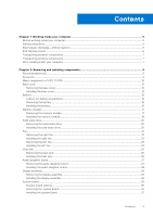
-ESD protection...6 ESD field service kit ...6 Transporting sensitive components...7 Transporting sensitive components...7 After working inside your computer...7 Chapter 2: Removing and installing components 9 Recommended tools...9 Screw list...9 Major components of XPS 17 9730...10 Base cover...12 - Dell XPS 17 9730 | Service Manual - Page 4
the BIOS from the F12 One-Time boot menu 62 Clearing CMOS settings...62 Chapter 5: Troubleshooting...63 Handling swollen Lithium-ion batteries...63 Locate the Service Tag or Express Service Code of your Dell computer 63 SupportAssist diagnostics...64 Built-in self-test (BIST)...64 M-BIST...64 LCD - Dell XPS 17 9730 | Service Manual - Page 5
operating system for shut-down instructions. 3. Disconnect your computer electrocuted. Standby power Dell products with standby power and has other advanced power management features. Unplugging, pressing, and holding done through the use of a field service electrostatic discharge (ESD) kit. When - Dell XPS 17 9730 | Service Manual - Page 6
obvious, such as intermittent problems or a shortened product Dell products, the sensitivity to static damage is now higher than in previous Dell of damage to recognize and troubleshoot is the intermittent (also called is known as bonding. Use only Field Service kits with a wrist strap, mat, and - Dell XPS 17 9730 | Service Manual - Page 7
protective anti-static mat at all times when servicing Dell products. In addition, it is critical to keep sensitive parts for a stable base, and point your toes out. 2. Tighten stomach muscles. Abdominal muscles support your spine when you lift, offsetting the force of the load. 3. Lift with your - Dell XPS 17 9730 | Service Manual - Page 8
2. Connect any external devices, peripherals, or cables you removed before working on your computer. 3. Replace any media cards, discs, or any other parts that you removed before working on your computer. 4. Connect your computer and all attached devices to their electrical outlets. 5. Turn on your - Dell XPS 17 9730 | Service Manual - Page 9
2 Removing and installing components NOTE: The images in this document may differ from your computer depending on the configuration you ordered. Recommended tools The procedures in this document may require the following tools: ● Phillips screwdriver #0 ● Phillips screwdriver #1 ● Torx #5 (T5) - Dell XPS 17 9730 | Service Manual - Page 10
Quantity 3 2 3 Right hinge M2.5x6 3 Type-C connector bracket M2x4 4 Wireless card bracket M2x4 1 System board M2x4 3 Antennas M2x2 8 Major components of XPS 17 9730 The following image shows the major components of XPS 17 9730. Screw image 10 Removing and installing components - Dell XPS 17 9730 | Service Manual - Page 11
1. Base cover 3. Solid-state drive thermal shield 5. Right fan 7. USB Type-C port bracket 9. Memory module 11. Palm-rest and keyboard assembly 2. Battery 4. M.2 2280 solid-state drive 6. Display-cable bracket 8. System board 10. Right antenna 12. Display assembly Removing and installing components - Dell XPS 17 9730 | Service Manual - Page 12
drive thermal shield 17. USB Type-C port bracket 19. Heat sink 14. M.2 2280 solid-state drive 16. Audio-daughter board 18. Left fan NOTE: Dell provides a list to warranty coverages purchased by the customer. Contact your Dell sales representative for purchase options. Base cover Removing the - Dell XPS 17 9730 | Service Manual - Page 13
CAUTION: Only use a plastic scribe to disengage and release the clips with the prying motion along the edges left corner, use a plastic scribe to pry the base cover in the direction of the arrows to release the base cover from the palm-rest and keyboard assembly. 3. Firmly hold the left side and the - Dell XPS 17 9730 | Service Manual - Page 14
5. Press and hold the power button for 20 seconds to ground the computer and drain the flea power. Installing the base cover Prerequisites About this task The following images indicate the location of the base cover and provide a visual representation of the installation procedure. Steps 1. Align - Dell XPS 17 9730 | Service Manual - Page 15
battery. ● Ensure any screws during the servicing of this product are not lost or release it as puncturing, bending, or crushing a lithium-ion battery can be dangerous. In such an instance, contact Dell technical support for assistance. See www.dell error appears and set the date and time on your - Dell XPS 17 9730 | Service Manual - Page 16
Steps 1. Disconnect the battery cable from the system board (if not disconnected earlier). 2. Open the display and press the power button for 5 seconds to drain the flea power. 3. Remove the seven screws (M2x4) that secure the battery to the palm rest and keyboard assembly. 4. Lift the battery off - Dell XPS 17 9730 | Service Manual - Page 17
. About this task The following image indicates the location of the memory modules and provides a visual representation of the removal procedure. Removing and installing components 17 - Dell XPS 17 9730 | Service Manual - Page 18
Steps 1. Lift the mylar that covers the memory module. 2. Use your fingertips to carefully spread apart the securing-clips on each end of the memory-module slot until the memory module pops up. 3. Slide and remove the memory module from the memory-module slot. NOTE: Repeat step 1 to step 3 to remove - Dell XPS 17 9730 | Service Manual - Page 19
Steps 1. Lift the mylar that covers the memory-module slot. 2. Align the notch on the memory module with the tab on the memory-module slot. 3. Slide the memory module firmly at an angle, into the memory-module slot. 4. Press the memory module down until it clicks into place. NOTE: If you do not hear - Dell XPS 17 9730 | Service Manual - Page 20
Solid-state drive Removing the solid-state drive Prerequisites 1. Follow the procedure in Before working inside your computer. 2. Remove the base cover. 3. Remove the battery. About this task The following image indicates the location of the solid-state drive and provides a visual representation of - Dell XPS 17 9730 | Service Manual - Page 21
Steps 1. Align the notch on the solid-state drive with the tab on the solid-state drive slot. 2. Slide the solid-state drive into the solid-state drive slot. 3. Using the alignment post, place the solid-state drive thermal shield over the solid-state drive. 4. Align the screw hole on the solid-state - Dell XPS 17 9730 | Service Manual - Page 22
Steps 1. Remove the two screws (M2x4) and the single screw (M1.6x4) that secure the fan to the system board and palm-rest and keyboard assembly. CAUTION: Do not hold the fan assembly at the center, as it may damage the center bearing. 2. Disconnect the fan cable from the system board. 3. Lift the - Dell XPS 17 9730 | Service Manual - Page 23
Steps 1. Connect the fan cable to the system board. 2. Align the screw holes on the fan with the screw holes on the system board and palm-rest and keyboard assembly. 3. Replace the two screws (M2x4) and the single screw (M1.6x4) to secure the fan to the system board and palm-rest and keyboard - Dell XPS 17 9730 | Service Manual - Page 24
Steps 1. Remove the two screws (M2x4) and the single screw (M1.6x4) that secure the fan to the system board and palm-rest and keyboard assembly. CAUTION: Do not hold the fan assembly at the center, as it may damage the center bearing. 2. Disconnect the fan cable from the system board. 3. Lift the - Dell XPS 17 9730 | Service Manual - Page 25
Steps 1. Align the screw holes on the fan with the screw holes on the system board and palm-rest and keyboard assembly. 2. Replace the two screws (M2x4) and the single screw (M1.6x4) to secure the fan to the system board and palm-rest and keyboard assembly. 3. Connect the fan cable to the system - Dell XPS 17 9730 | Service Manual - Page 26
Steps 1. Remove the seven screws (M2.5x5) in reverse sequential order (7 > 6 > 5 > 4 > 3 > 2 > 1) as indicated by the numbers on the heat sink. 2. Lift the heat sink off the system board. Installing the heat sink Prerequisites CAUTION: Incorrect alignment of the heat sink can damage the system board - Dell XPS 17 9730 | Service Manual - Page 27
Steps 1. Align the screw holes on the heat sink with the screw holes on the system board. 2. In sequential order (1 > 2 > 3 > 4 > 5 > 6 > 7), as indicated by the numbers on the heat sink, install the seven screws (M2.5x5) to secure the heat sink to the system board. Next steps 1. Install the base - Dell XPS 17 9730 | Service Manual - Page 28
Steps 1. Remove the three screws (M2x4) that secure the audio-daughter board to the palm-rest and keyboard assembly. 2. Lift the audio-daughter board off the palm-rest and keyboard assembly. Installing the audio-daughter board Prerequisites About this task The following image indicates the location - Dell XPS 17 9730 | Service Manual - Page 29
Steps 1. Align the screw hole on the audio-daughter board with the screw hole on the palm-rest and keyboard assembly. 2. Replace the three screws (M2x4) that secure the audio-daughter board to the palm-rest and keyboard assembly. Next steps 1. Install the base cover. 2. Follow the procedure in After - Dell XPS 17 9730 | Service Manual - Page 30
30 Removing and installing components - Dell XPS 17 9730 | Service Manual - Page 31
Steps 1. Remove the two screws (M2x4) that secure the display-cable bracket to the system board. 2. Lift the display-cable bracket off the system board. 3. Disconnect the camera connector and the display connector from the system board. 4. Remove the three screws (M2.5x6) that secure the left - Dell XPS 17 9730 | Service Manual - Page 32
Installing the display assembly Prerequisites About this task The following images indicate the location of the display assembly and provide a visual representation of the installation procedure. 32 Removing and installing components - Dell XPS 17 9730 | Service Manual - Page 33
Removing and installing components 33 - Dell XPS 17 9730 | Service Manual - Page 34
Steps 1. Slide the palm-rest and keyboard assembly under the display hinges. 2. Fold back the hinges and align the screw holes on the palm-rest assembly with the screw holes on the display hinges. 3. Replace the three screws (M2.5x6) to secure the left display hinge to the system board and the palm- - Dell XPS 17 9730 | Service Manual - Page 35
connector Removing the system board Prerequisites 1. Follow the procedure in Before working inside your computer. NOTE: The Service Tag of your computer is stored in the system board. Enter the Service Tag in the BIOS setup program after you replace the system board. NOTE: Replacing the system board - Dell XPS 17 9730 | Service Manual - Page 36
About this task The following images indicate the location of the system board and provide a visual representation of the removal procedure. 36 Removing and installing components - Dell XPS 17 9730 | Service Manual - Page 37
Lift the system board off the palm-rest and keyboard assembly. Installing the system board Prerequisites NOTE: The Service Tag of your computer is stored in the system board. Enter the Service Tag in the BIOS setup program after you replace the system board. NOTE: Replacing the system board removes - Dell XPS 17 9730 | Service Manual - Page 38
38 Removing and installing components - Dell XPS 17 9730 | Service Manual - Page 39
the antenna cables to the wireless module. The following table provides the antenna-cable color scheme for the wireless card that is supported by your computer. Table 2. Antenna-cable color scheme Connectors on the wireless card Main Auxiliary Antenna-cable color Silkscreen marking White Black - Dell XPS 17 9730 | Service Manual - Page 40
Antenna Removing the antenna Prerequisites 1. Follow the procedure in Before working inside your computer. NOTE: The Service Tag of your computer is stored in the system board. Enter the Service Tag in the BIOS setup program after you replace the system board. NOTE: Replacing the system board - Dell XPS 17 9730 | Service Manual - Page 41
cable to the palm-rest and keyboard assembly. 4. Note the routing of the antenna cables along the routing guides on the palm-rest and keyboard assembly. 5. Remove the antenna cable from the routing guides on the palm-rest and keyboard assembly. 6. Lift the left and the right antenna, along with its - Dell XPS 17 9730 | Service Manual - Page 42
Steps 1. Place the antennas into the slots on the palm-rest and keyboard assembly. 2. Route the antenna cable through the routing guides on the palm-rest and keyboard assembly. NOTE: Route the antenna cable under the keyboard-control cable. 3. Adhere the tapes that secure the antenna cable - Dell XPS 17 9730 | Service Manual - Page 43
7. Install the solid-state drive. 8. Install the memory module. 9. Install the battery. 10. Install the base cover. 11. Follow the procedure in After working inside your computer. Palm-rest and keyboard assembly Palm-rest and keyboard assembly Prerequisites 1. Follow the procedure in Before working - Dell XPS 17 9730 | Service Manual - Page 44
Next steps 1. Install the antennas. 2. Install the system board. 3. Install the display assembly. 4. Install the audio-daughter board. 5. Install the left fan. 6. Install the right fan. 7. Install the heat sink. 8. Install the solid-state drive. 9. Install the memory module. 10. Install the battery. - Dell XPS 17 9730 | Service Manual - Page 45
3 Drivers and downloads When troubleshooting, downloading or installing drivers it is recommended that you read the Dell Knowledge Base article, Drivers and Downloads FAQ 000123347. Drivers and downloads 45 - Dell XPS 17 9730 | Service Manual - Page 46
directly to a specific device (for example: USB flash drive, external optical drive, or external storage device). During the Power-on Self Test (POST), when the Dell logo appears, you can: 46 System setup - Dell XPS 17 9730 | Service Manual - Page 47
may or may not be displayed. Table 4. System setup options-System information menu Overview for XPS 17 9730 BIOS Version Service Tag Asset Tag Manufacture Date Ownership Date Express Service Code Ownership Tag Signed Firmware Update Battery Primary Battery Level Battery State Health AC Adapter - Dell XPS 17 9730 | Service Manual - Page 48
Table 4. System setup options-System information menu (continued) Overview for XPS 17 9730 PROCESSOR Processor Type Displays the processor type. Maximum Clock Speed Displays the maximum processor clock speed. Minimum Clock Speed Displays the minimum processor clock speed. - Dell XPS 17 9730 | Service Manual - Page 49
Date/Time Date Time Camera Enable Camera Sets the computer date in MM/DD/YYYY format. Changes to the date Support Enables or disables the Thunderbolt Technology feature and associated ports and adapters. Default: ON Enable Thunderbolt Boot Support Enables or disables Thunderbolt adapter features - Dell XPS 17 9730 | Service Manual - Page 50
Enable USB Boot Support is selected. Enable Thunderbolt Technology Support Enables or disables the Thunderbolt Technology feature and associated ports and the LAN on the external ports of the connected Type-C Dell docking station. Default: ON Miscellaneous Devices Enable Fingerprint Reader Device - Dell XPS 17 9730 | Service Manual - Page 51
UEFI Network Stack Enable UEFI Network Stack When enabled, UEFI networking protocols are installed and available, allowing pre-OS and early OS networking features to use any enabled NICs. This may be used without PXE turned on. Default: ON Wireless Radio Control Control WLAN radio Enables to - Dell XPS 17 9730 | Service Manual - Page 52
automatically extract Boot URL from the Dynamic Host Configuration Protocol (DHCP) or manually read Boot URL as provided by the user. By default, Auto Mode By default, Optimized is selected. USB Wake Support Wake on Dell USB-C Dock Enables connecting a Dell USB-C Dock to wake the computer from - Dell XPS 17 9730 | Service Manual - Page 53
has been removed from the computer. Block Boot Until Cleared Enables or disables the "Block Boot Until Cleared" setting. Default: ON NOTE: When this feature is turned on, the computer will not boot up until the chassis intrusion is cleared. If the Administrator password is set, Setup has to be - Dell XPS 17 9730 | Service Manual - Page 54
UEFI SMM Security Mitigation protections. Default: OFF NOTE: This feature may cause compatibility issues or loss of functionality with some legacy disable the BIOS module interface of the optional Absolute Persistence Module service from Absolute Software. By default, Enable Absolute is selected. - Dell XPS 17 9730 | Service Manual - Page 55
Lockout Enables or disables the master password support. Default: OFF Allow Non-Admin ) revert of NVMe hard drives from the Dell Security Manager prompt. Default: OFF Table 13 work if the Boot Block is damaged. In addition, this feature cannot work in the event of EC corruption, ME corruption, - Dell XPS 17 9730 | Service Manual - Page 56
of certain system errors. Default: ON BIOSConnect BIOSConnect Enables or disables cloud Service OS recover if the main operating system fails to boot with the On Date Configures the Ownership date. Default: OFF Diagnostics OS Agent Requests Enables or disables the capability of the Dell OS - Dell XPS 17 9730 | Service Manual - Page 57
F12 keys scan the code for their secondary functions. Keyboard Illumination Keyboard Illumination Configures the operating mode of the keyboard illumination feature. By default, Bright is selected. Keyboard Backlight Timeout on AC Keyboard Backlight Timeout on AC Configures the timeout value for - Dell XPS 17 9730 | Service Manual - Page 58
Pass-Through MAC Address Pass-Through Replaces the external NIC MAC address (in a supported dock or dongle) with the selected MAC address from the computer. By default Backlight Sign of Life. Default: ON Table 17. System setup options-Virtualization menu Virtualization Intel Virtualization - Dell XPS 17 9730 | Service Manual - Page 59
Table 18. System setup options-Performance menu (continued) Performance Enable Intel SpeedStep Technology Enables or disables the Intel SpeedStep Technology to dynamically adjust processor voltage and core frequency, decreasing average power consumption and heat production. Default: ON C-States - Dell XPS 17 9730 | Service Manual - Page 60
make changes to the BIOS settings of your computer. You can create a system password and a setup password to secure your computer. CAUTION: The password features provide a basic level of security for the data on your computer. CAUTION: Anyone can access the data that is stored on your computer if - Dell XPS 17 9730 | Service Manual - Page 61
the BIOS in Windows Steps 1. Go to www.dell.com/support. 2. Click Product support. In the Search support box, enter the Service Tag of your computer, and then click Search. NOTE: If you do not have the Service Tag, use the SupportAssist feature to automatically identify your computer. You can also - Dell XPS 17 9730 | Service Manual - Page 62
Update Utility appears. 8. Follow the on-screen instructions to complete the BIOS update. Updating the BIOS (key does not have to be bootable) ● BIOS executable file that you downloaded from the Dell Support website and copied to the root of the USB drive ● AC power adapter that is connected to - Dell XPS 17 9730 | Service Manual - Page 63
Service Code. To view relevant support resources for your Dell computer, we recommend entering the Service Tag or Express Service Code at www.dell.com/support. For more information on how to find the Service Tag for your computer, see Locate the Service Tag for your Dell Laptop. Troubleshooting - Dell XPS 17 9730 | Service Manual - Page 64
: M-BIST can be manually initiated before POST (Power Dell laptops have a built-in diagnostic tool that helps you determine if the screen abnormality you are experiencing is an inherent problem with the LCD (screen) of the Dell laptop or with the video card (GPU) and PC settings. 64 Troubleshooting - Dell XPS 17 9730 | Service Manual - Page 65
Test (BIST). How to invoke LCD BIST Test 1. Power off the Dell laptop. 2. Disconnect any peripherals that are connected to the laptop. problem persists, replace the memory module Reseat and swap memory modules between the slots. If the problem persists, replace the memory module. Troubleshooting - Dell XPS 17 9730 | Service Manual - Page 66
Support website to troubleshoot and fix your computer when it fails to boot into their primary operating system due to software or hardware failures. For more information about the Dell SupportAssist OS Recovery, see Dell SupportAssist OS Recovery User's Guide at www.dell.com/serviceabilitytools - Dell XPS 17 9730 | Service Manual - Page 67
the Knowledge Base Resource at www.dell.com/ support. Real-Time Clock (RTC Reset) The Real Time Clock (RTC) reset function allows you or the service technician to recover Dell systems from No POST/No (30) seconds . The system RTC Reset occurs after you release the power button. Troubleshooting 67 - Dell XPS 17 9730 | Service Manual - Page 68
through videos, manuals and documents. In Windows search, type Contact Support, and press Enter. www.dell.com/support/windows Your Dell computer is uniquely identified by a Service Tag or Express Service Code. To view relevant support resources for your Dell computer, enter the Service Tag or
-
 1
1 -
 2
2 -
 3
3 -
 4
4 -
 5
5 -
 6
6 -
 7
7 -
8
-
9
-
10
-
11
-
12
-
13
-
14
-
15
-
16
-
17
-
18
-
19
-
20
-
21
-
22
-
23
-
24
-
25
-
26
-
27
-
28
-
29
-
30
-
31
-
32
-
33
-
34
-
35
-
36
-
37
-
38
-
39
-
40
-
41
-
42
-
43
-
44
-
45
-
46
-
47
-
48
-
49
-
50
-
51
-
52
-
53
-
54
-
55
-
56
-
57
-
58
-
59
-
60
-
61
-
62
-
63
-
64
-
65
-
66
-
67
-
68
 |
 |

XPS 17 9730
Service Manual
Regulatory Model: P92F
Regulatory Type: P92F004
February 2023
Rev. A00