Denon AVR 3802 Owners Manual - Page 9
SETTING UP THE SYSTEM, Remote control unit - setup
 |
View all Denon AVR 3802 manuals
Add to My Manuals
Save this manual to your list of manuals |
Page 9 highlights
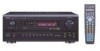
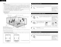
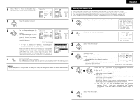
ENGLISH Remote control unit • For details on the functions of these parts, refer to the pages given in parentheses ( ). POWER OFF ON / SOURCE RC-884 REMOTE CONTROL UNIT Remote control signal transmitter 16) Power button 22) DISPLAY/SURR. PARA button 28) System setup/ system button 10) Tuner system/ system button 10) System buttons 33) ENTER/system button 10) Speaker selector / PTY button .....(30) TEST TONE / RDS button 27) Surround mode buttons 30) Input mode selector buttons .......(23) SYSTEM CALL buttons 19) TV CD CDR/MD/ TAPE RECEIVER VCR DBS/CABLE VDP DVD DISPLAY SURR. PARA. SETUP TUNING MENU OSD RETURN A/B MEMORY BAND MODE CHANNEL VOLUME TUNING + + SKIP ENTER - SKIP SHIFT MUTING TUNER 1 PHONO 2 CDR/ TAPE VDP 4 5 VCR-1 VCR-2 / V.AUX 7 8 - CD 3 DVD 6 TV/DBS 9 TV/ VCR RDS TEST TONE DOLBY/DTS SURROUND 0 PTY SPEAKER +10 RT OUTPUT SURROUND DSP SIMU. 5CH / 7CH STEREO 6.1 / 7.1 SURROUND DIRECT STEREO MODE INPUT ANALOG EXT.IN SYSTEM CALL CALL 1 CALL 2 BACKLIGHT Mode selector buttons 17) MENU/OSD button 25) RETURN/MEMORY/system button 33) Master volume control buttons 23) MUTING button 24) Input source selector buttons 23) OUTPUT / RT button 24) BACKLIGHT button 7 SETTING UP THE SYSTEM • Once all connections with other AV components have been completed as described in "CONNECTIONS" (see pages 4 to 8), make the various settings described below on the monitor screen using the AVR-3802's on-screen display function. These settings are required to set up the listening room's AV system centered around the AVR-3802. • Use the following buttons to set up the system: DISPLAY SURR. PARA. SETUP TUNING MENU OSD RETURN A/B MEMORY BAND CHANNEL MODE VOLUME TUNING + + SKIP ENTER - SKIP TUNER SHIFT MUTING PHONO - CD SYSTEM SETUP button Press this to display the system setup menu. CURSOR buttons F and G: Use these to move the cursors (F and G) to the left and right on the screen. D and H: Use these to move the cursors (D and H) to the up and down on the screen. ENTER button Press this to switch the display. Also use this button to complete the setting. • System setup items and default values (set upon shipment from the factory) System setup Default settings q Power AMP Assignment Set this to switch the surround back channel's power amplifier for use for multi-zone. Surround Back Speaker Configuration Input the combination of speakers in your system and their corresponding sizes (SMALL for regular speakers, LARGE for full-size, full-range) to automatically set the composition of the signals output from the speakers and the frequency response. Front Sp. Large Center Sp. Small Sub Woofer Surround Sp. A /B Surround Back Sp. Yes Small Small / 2spkrs w (Surround Use this function when using multiple surround speaker combinations for more ideal surround sound. Once the combinations of surround Surround mode DOLBY/ DTS SURROUND 5CH/7CH STEREO DSP SIMULATION EXT. IN - - Speaker speakers to be used for the different surround Setting) modes are preset, the surround speakers are selected automatically according to the surround Surround mode. speaker A A A A - - Crossover Frequency (Subwoofer mode) e SB CH Auto Flag Detect Set the frequency (Hz) below which the bass sound of the various speakers is to be output from the subwoofer. This selects the subwoofer speaker for playing deep bass signals. Set the method of playing the surround backchannel for digital signals. 80 Hz LFE DTS-ES / 6.1 Source Auto Flag Detect Mode = OFF r Delay Time This parameter is for optimizing the timing with which the audio signals are produced from the speakers and subwoofer according to the listening position. Front L & R 3.6 m (12 ft) Center 3.6 m (12 ft) Sub Woofer 3.6 m (12 ft) Surround L & R 3.0 m (10 ft) SBL & SBR 3.0 m (10 ft) t Channel Level This adjusts the volume of the signals output from the speakers and subwoofer for the different channels in order to obtain optimum effects. Front L 0 dB Front R 0 dB Center Surround L Surround R Surround Back L Surround Back R Subwoofer 0 dB 0 dB 0 dB 0 dB 0 dB 0 dB y Digital In Input source CD This assigns the digital input jacks for the different DVD TV/DBS CDR /TAPE VDP VCR-1 VCR-2 - Assignment input sources. Digital Inputs COAXIAL OPTICAL 1 OPTICAL 2 OPTICAL 3 OFF OFF OFF - u Multi vol. Level This sets the output level for the multi output jacks. 0 dB i On Screen Display o Auto Tuner Preset This sets whether or not to display the on-screen display that appears on the monitor screen when the controls on the remote control unit or main unit are operated. FM stations are received automatically and stored in the memory. A1 ~ A8 B1 ~ B8 C1 ~ C8 D1 ~ D8 E1 ~ E8 On Screen Display = ON 87.5 / 89.1 / 98.1 / 108.0 / 90.1 / 90.1 / 90.1 / 90.1 MHz 522 / 603 / 999 / 1404 / 1611 kHz, 90.1 / 90.1 MHz 90.1 MHz 90.1 MHz 90.1 MHz 9
-
 1
1 -
2
-
3
-
 4
4 -
 5
5 -
 6
6 -
 7
7 -
 8
8 -
 9
9 -
 10
10 -
 11
11 -
 12
12 -
 13
13 -
 14
14 -
15
-
16
-
17
-
18
-
19
-
20
-
21
-
22
-
23
-
24
-
25
-
26
-
27
-
28
-
29
-
30
-
31
-
32
-
33
-
34
-
35
-
36
-
37
-
38
-
39
-
40
-
41
-
42
-
43
-
44
-
45
-
46
-
47
-
48
-
49
-
50
-
51
-
52
-
53
-
54
-
55
-
56
-
57
-
58
-
59
-
60
-
61
-
62
-
63
-
64
-
65
-
66
-
67
-
68
-
69
-
70
-
71
-
72
-
73
-
74
-
75
-
76
-
77
-
78
-
79
-
80
-
81
-
82
 |
 |
