Denon AVR-3803 Owners Manual - Page 25
Setting the Video Setup, Setting the Component In Assign. - factory reset
 |
View all Denon AVR-3803 manuals
Add to My Manuals
Save this manual to your list of manuals |
Page 25 highlights
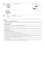
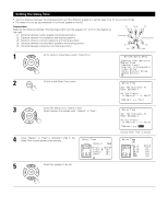
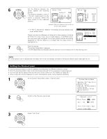
NOTES: • The OPTICAL 4 and 5 jacks on the AVR-3803/1083's rear panel are equipped with an optical digital output jack for recording digital signals on a CD recorder, MD recorder or other digital recorder. Use this for digital recording between a digital audio source (stereo - 2 channel) and a digital audio recorder. • Do not connect the output of the component connected to the OPTICAL 4 OUT jack on the AVR-3803/1083's rear panel to any jack other than the OPTICAL 4 IN jack. • Do not connect the output of the component connected to the OPTICAL 5 OUT jack on the AVR-3803/1083's rear panel to any jack other than the OPTICAL 5 IN jack. • "PHONO" and "TUNER" cannot be selected on the Digital In Assignment. Setting the Video Setup • This setting assigns the color difference (component) video input jacks of the AVR-3803/1083 for the different input sources. [1] Setting the Component In Assign. 1 At the System Setup Menu select "Video Setup" and press the ENTER button. 2 The "Video Setup" screen appears. Select "Component In Assign." and press the ENTER button. 3 Switch to the Component In Assign. screen. 4 Select the component (Y, PB/CB and PR/CR) video input terminal to be assigned to the input source. q Input source selection w Component video terminal selection Select "NONE" for sources for which the component (Y, PB/CB and PR/CR) video input is not to be used. When the default, "Yes", is selected, the settings are reset to the factory defaults. 5 Press the ENTER button to complete the setting. At the "Video Setup" screen, select "Exit" and press the ENTER button. The System Setup Menu reappears. 25
-
 1
1 -
2
-
3
-
4
-
5
-
6
-
7
-
8
-
9
-
10
-
11
-
12
-
13
-
14
-
15
-
16
-
17
-
18
-
19
-
 20
20 -
 21
21 -
 22
22 -
 23
23 -
 24
24 -
 25
25 -
 26
26 -
 27
27 -
 28
28 -
 29
29 -
 30
30 -
31
-
32
-
33
-
34
-
35
-
36
-
37
-
38
-
39
-
40
-
41
-
42
-
43
-
44
-
45
-
46
-
47
-
48
-
49
-
50
-
51
-
52
-
53
-
54
-
55
-
56
-
57
-
58
-
59
-
60
-
61
-
62
-
63
-
64
-
65
-
66
-
67
-
68
-
69
-
70
-
71
-
72
-
73
-
74
-
75
-
76
-
77
-
78
-
79
-
80
-
81
-
82
-
83
-
84
 |
 |
