Denon AVR-991 Owners Manual - English - Page 98
Rear panel
 |
UPC - 883795001397
View all Denon AVR-991 manuals
Add to My Manuals
Save this manual to your list of manuals |
Page 98 highlights
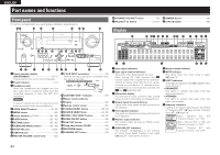
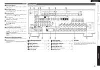
Simple version Basic version ENGLISH Display Q2 Sleep timer indicator This lights when the sleep mode is selected (vpage 53). Q3 RESTORER indicator This lights when the RESTORER mode is selected (vpage 76). Q4 ZONE2 indicators This lights up when ZONE2 (separate room) power is turned on (vpage 60). Q5 AL24 indicator This lights when AL24 Processing Plus (vpage 104) is activated. Q6 Input mode indicators Set the audio input modes for the different input sources (vpage 69). Q7 HDMI indicator This lights when playing using HDMI connections. Q8 Tuner reception mode indicators These light according to the reception conditions when the input source is set to "TUNER". STEREO : In the FM mode, this light when receiving stereo broadcasts. TUNED : Lights when the broadcast is properly tuned in. AUTO : This light when in the auto tuning mode. Q9 Recording output source indicator This lights when the REC OUT mode is selected. W0 Decoder indicators These light when the respective decoders are operating. Rear panel See the page indicated in parentheses ( ). Q4 Q3 Q2 Q1 Q0 o i q w e r t q FM/AM antenna terminals 20) w Analog audio connectors 16 - 18, 21) e ZONE2 connectors 59) r PRE OUT connectors 5, 48 - 50) t SIGNAL GND terminal 21) y Speaker terminals 5, 48 - 50) u AC inlet (AC IN 5) i HDMI connectors 15) o COMPONENT VIDEO connectors 16, 17) Q0 Digital audio connectors 16 - 18) Q1 ETHERNET connector 22) Q2 DOCK CONTROL jack 19) Q3 S-VIDEO/VIDEO connectors 16 - 19) Q4 SIRIUS connector 20) y u NOTE Do not touch the inner pins of the connectors on the rear panel. Electrostatic discharge may cause permanent damage to the unit. Advanced version Information 95
-
 1
1 -
2
-
3
-
4
-
5
-
6
-
7
-
8
-
9
-
10
-
11
-
12
-
13
-
14
-
15
-
16
-
17
-
18
-
19
-
20
-
21
-
22
-
23
-
24
-
25
-
26
-
27
-
28
-
29
-
30
-
31
-
32
-
33
-
34
-
35
-
36
-
37
-
38
-
39
-
40
-
41
-
42
-
43
-
44
-
45
-
46
-
47
-
48
-
49
-
50
-
51
-
52
-
53
-
54
-
55
-
56
-
57
-
58
-
59
-
60
-
61
-
62
-
63
-
64
-
65
-
66
-
67
-
68
-
69
-
70
-
71
-
72
-
73
-
74
-
75
-
76
-
77
-
78
-
79
-
80
-
81
-
82
-
83
-
84
-
85
-
86
-
87
-
88
-
89
-
90
-
91
-
92
-
 93
93 -
 94
94 -
 95
95 -
 96
96 -
 97
97 -
 98
98 -
 99
99 -
 100
100 -
 101
101 -
 102
102 -
 103
103 -
104
-
105
-
106
-
107
-
108
-
109
-
110
-
111
-
112
-
113
-
114
-
115
-
116
 |
 |
