Epson DM-D210 Technical Reference Guide - Page 65
cable in the support., Connect the cable to the TM printer. When the cable is long
 |
View all Epson DM-D210 manuals
Add to My Manuals
Save this manual to your list of manuals |
Page 65 highlights
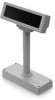
Chapter 2 Setup 3 Pass the cable for the this product through the hole on fixing plate A and fix the cable at the bottom as shown below. 2 4 Peel off the affixing tapes and secure it to the mounting position. When using screws to attach it on the counter, use the screws to secure it to the mounting position. 5 Connect the cable to the TM printer. When the cable is long, put the excess part of the cable in the support. For the RS-232/USB model, the end of the connector of the unused cable should be capped, and then bundled to be stored inside support. 65
-
 1
1 -
2
-
3
-
4
-
5
-
6
-
7
-
8
-
9
-
10
-
11
-
12
-
13
-
14
-
15
-
16
-
17
-
18
-
19
-
20
-
21
-
22
-
23
-
24
-
25
-
26
-
27
-
28
-
29
-
30
-
31
-
32
-
33
-
34
-
35
-
36
-
37
-
38
-
39
-
40
-
41
-
42
-
43
-
44
-
45
-
46
-
47
-
48
-
49
-
50
-
51
-
52
-
53
-
54
-
55
-
56
-
57
-
58
-
59
-
 60
60 -
 61
61 -
 62
62 -
 63
63 -
 64
64 -
 65
65 -
 66
66 -
 67
67 -
 68
68 -
 69
69 -
 70
70 -
71
-
72
-
73
-
74
-
75
-
76
-
77
-
78
-
79
-
80
-
81
-
82
-
83
-
84
-
85
-
86
-
87
-
88
-
89
-
90
-
91
-
92
-
93
-
94
-
95
-
96
-
97
-
98
-
99
-
100
-
101
-
102
-
103
-
104
-
105
-
106
-
107
 |
 |

65
Chapter 2
Setup
2
3
Pass the cable for the this product through the hole on fixing plate A and fix the cable
at the bottom as shown below.
4
Peel off the affixing tapes and secure it to the mounting position. When using screws
to attach it on the counter, use the screws to secure it to the mounting position.
5
Connect the cable to the TM printer. When the cable is long, put the excess part of the
cable in the support.
For the RS-232/USB model, the end of the connector of the unused cable should be
capped, and then bundled to be stored inside support.