Epson DM-D210 Technical Reference Guide - Page 74
Connecting, USB (Self Powered)
 |
View all Epson DM-D210 manuals
Add to My Manuals
Save this manual to your list of manuals |
Page 74 highlights
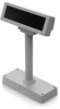
Chapter 2 Setup Connecting This section explains how to connect to the system by connection patterns. The illustrations used here are for DM-D110/DP-110, but you can still use them as your reference for DMD210/DP-210. CAUTION When attaching or removing the cables, make sure you turn off the power to the customer display and the system. When connecting or removing the AC adapter to the DC cable connector, make sure that the AC adapter's power cord is unplugged from the outlet. When connecting or removing the DC cable of the AC adapter, make sure you hold the connector part. If you pull the cable part, you may damage the cable. USB (Self Powered) 2 DM-D110/DM-D210 Ferrite core USB cable RS-232 cable DM-D110 DM-D210 DP-110 DP-210 Computer AC adapter Power cord DP-110/DP-210 USB cable Remove the cap Attach the ferrite core Connect to the computer RS-232 cable Remove the cap Connect to the DM-D connector of DP-110/DP-210 DM-D connector Connect the RS-232 cable of DM-D110/DM-D210 Power supply connector Connect the AC adapter Extension power cable connec- Not used tor Computer interface connector Not used Printer interface connector Not used JP1 Not setting JP2 Not setting 74
-
 1
1 -
2
-
3
-
4
-
5
-
6
-
7
-
8
-
9
-
10
-
11
-
12
-
13
-
14
-
15
-
16
-
17
-
18
-
19
-
20
-
21
-
22
-
23
-
24
-
25
-
26
-
27
-
28
-
29
-
30
-
31
-
32
-
33
-
34
-
35
-
36
-
37
-
38
-
39
-
40
-
41
-
42
-
43
-
44
-
45
-
46
-
47
-
48
-
49
-
50
-
51
-
52
-
53
-
54
-
55
-
56
-
57
-
58
-
59
-
60
-
61
-
62
-
63
-
64
-
65
-
66
-
67
-
68
-
 69
69 -
 70
70 -
 71
71 -
 72
72 -
 73
73 -
 74
74 -
 75
75 -
 76
76 -
 77
77 -
 78
78 -
 79
79 -
80
-
81
-
82
-
83
-
84
-
85
-
86
-
87
-
88
-
89
-
90
-
91
-
92
-
93
-
94
-
95
-
96
-
97
-
98
-
99
-
100
-
101
-
102
-
103
-
104
-
105
-
106
-
107
 |
 |
