Epson TM-L500A Technical Reference Guide: RFID - Page 27
Printable Area, Printing and Cutting Positions
 |
View all Epson TM-L500A manuals
Add to My Manuals
Save this manual to your list of manuals |
Page 27 highlights
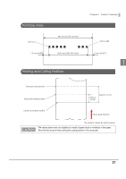
Printable Area Dot no.3 1.5 mm {0.059"} 54.0 mm {2.13"} ± 0.5 mm 50.8 mm {2.00"} (407 dots) Printing and Cutting Positions Chapter 1 Product Overview Dot no.409 1.7 mm {0.067"} 1 Manual-cutter position Autocutter blade position Approx. 16 mm Approx. 31 mm Center of the print dotline Paper feed direction The numeric values are typical values. The values above may vary slightly as a result of paper slack or variations in the paper. Take this into account when setting the cutting position of the autocutter. 27
-
 1
1 -
2
-
3
-
4
-
5
-
6
-
7
-
8
-
9
-
10
-
11
-
12
-
13
-
14
-
15
-
16
-
17
-
18
-
19
-
20
-
21
-
 22
22 -
 23
23 -
 24
24 -
 25
25 -
 26
26 -
 27
27 -
 28
28 -
 29
29 -
 30
30 -
 31
31 -
 32
32 -
33
-
34
-
35
-
36
-
37
-
38
-
39
-
40
-
41
-
42
-
43
-
44
-
45
-
46
-
47
-
48
-
49
-
50
-
51
-
52
-
53
-
54
-
55
-
56
-
57
-
58
-
59
-
60
-
61
-
62
-
63
-
64
-
65
-
66
-
67
-
68
-
69
-
70
-
71
-
72
-
73
-
74
-
75
-
76
-
77
-
78
-
79
-
80
-
81
-
82
-
83
-
84
-
85
-
86
-
87
-
88
-
89
-
90
-
91
-
92
-
93
-
94
-
95
-
96
-
97
-
98
-
99
-
100
-
101
-
102
-
103
-
104
-
105
-
106
-
107
-
108
-
109
-
110
-
111
-
112
-
113
-
114
 |
 |

Chapter 1
Product Overview
27
1
Printable Area
Printing and Cutting Positions
The values above may vary slightly as a result of paper slack or variations in the paper.
Take this into account when setting the cutting position of the autocutter.
54.0 mm {2.13
"
} ± 0.5 mm
50.8 mm {2.00
"
} (407 dots)
1.5 mm {0.059
"
}
1.7 mm {0.067
"
}
Dot no.3
Dot no.409
Autocutter blade position
Approx. 31 mm
Approx.
16 mm
Manual-cutter position
Center of the print dotline
Paper feed direction
The numeric values are typical values.