Fagor 24 Inch Dual Fuel User Manual - Page 13
Electrical Connection
 |
View all Fagor 24 Inch Dual Fuel manuals
Add to My Manuals
Save this manual to your list of manuals |
Page 13 highlights
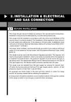
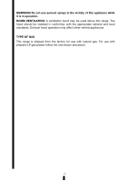
For a situation where the appliance is between two cabinets and the anti-tip device cannot be fitted, we suggest securing the range by screwing through both sides of the cabinets into the sides of the cooker. The installation screws should be fitted as follows. Position the oven between the cupboards in its final position, then mark the location of the pilot hole inside the cupboard. Use a 3.5mm diameter drill bit to drill the pilot hole through the cupboard and both sides of the range. Before drilling, check your measurements to ensure the pilot holes are located within the area specified in the installation diagram. A drilled hole in the side of the range, which is outside the specified area, may void the warranty. Inspect cabinets thoroughly before drilling to avoid damage to electrical wires or gas lines. Fix two 12 gauge x 40mm long self tapping screws through the pilot holes inside both cabinets and into the side of the range. Note: Required screw length is based on cupboard thickness of 20mm, and gap between cupboard and range of 10mm. Screw length could vary depending on cupboard material thickness and gap between range and cupboards. Note: The screws must be accessible for removal. 2.4 ELECTRICAL CONNECTION WARNING! ELECTRICAL SHOCK HAZARD Disconnect electrical power at the breaker box or fuse box before installing this appliance. Please make sure the unit is properly grounded for safety. Use copper conductors only. Failure to follow these instructions could result in serious injury or death. CAUTION Label all wires prior to disconnecting when servicing controls. Wiring errors can cause improper and dangerous operation. Always verify proper operation after servicing. The range is fitted with an approved 15 Amp flexible cord which must be connected to a correctly grounded power line. The manufacturer is not liable for any direct or indirect damage caused by faulty installation or connection. It is therefore necessary that all installation and connection operations are carried out by qualified personnel complying with the applicable local and general regulations. The wire section on the cable must not be less than 1.5mm (3×1.5 cable). Use only the cables available at our service centers. 13
-
 1
1 -
2
-
3
-
4
-
5
-
6
-
7
-
 8
8 -
 9
9 -
 10
10 -
 11
11 -
 12
12 -
 13
13 -
 14
14 -
 15
15 -
 16
16 -
 17
17 -
 18
18 -
19
-
20
-
21
-
22
-
23
-
24
-
25
-
26
-
27
-
28
-
29
-
30
-
31
-
32
-
33
-
34
-
35
-
36
-
37
-
38
-
39
-
40
-
41
-
42
-
43
-
44
-
45
-
46
-
47
-
48
-
49
-
50
-
51
-
52
-
53
-
54
-
55
-
56
-
57
-
58
-
59
-
60
-
61
-
62
-
63
-
64
-
65
-
66
-
67
-
68
-
69
-
70
-
71
-
72
-
73
-
74
-
75
-
76
-
77
-
78
 |
 |
