Fisher and Paykel DE70FA1 Dryers DE70FA* & DG70FA* User Guide (English, Sp - Page 24
Power Supply Cord Requirements for U.S.A
 |
View all Fisher and Paykel DE70FA1 manuals
Add to My Manuals
Save this manual to your list of manuals |
Page 24 highlights
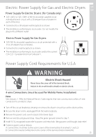
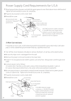
Power Supply Cord Requirements for U.S.A 7 Attach ground wire of power cord with the green ground screw (hole above strain relief bracket). Tighten all terminal block screws (3) completely. 8 Properly secure power cord to strain relief. 9 Reinstall the cover. Remove ground strap and discard. Keep green ground screw Screws (3) Hot wire Relocate green ground screw here L1 N Green or yellow wire L2 Strain relief bracket Cover Hot wire Neutral (white) /", UL recognized strain relief 4 #10 AWG minimum copper conductors or 120/240V 30A power supply cord kit marked for use with dryers & provided with closed loop or spade terminals with upturned ends (not supplied) 3-Wire Connections If required, by local code, install external ground (not provided) to grounded metal, cold water pipe, or other established ground determined by a qualified electrician. 1 Turn off the circuit breaker(s) (30 amp) or remove the dryer's circuit fuse at the electrical box. 2 Be sure the dryer cord is unplugged from the wall. 3 Remove the power cord cover located at the lower back. 4 Install /" UL recognized strain relief to power cord entry hole. Bring power cord through strain relief. 5 Connect power cord as follows: A. Connect the 2 hot lines to the outer screws of the terminal block (marked L1 and L2). B. Connect the neutral (white) line to the center of the terminal block (marked N). 6 Be sure ground strap is connected to neutral (center) terminal of block and to green ground screw on cabinet rear. Tighten all terminal block screws (3) completely. 7 Properly secure power cord to strain relief. 8 Reinstall the cover. Ground strap Green ground screw Hot wire Strain relief bracket L1 Screws L2 (3) /", UL recognized strain relief 3 #10 AWG minimum copper conductors or 120/240V 30A power Neutral Hot wire (white) supply cord kit marked for use with dryers & provided with closed loop or spade terminals with upturned Cover ends (not supplied) 24
-
 1
1 -
2
-
3
-
4
-
5
-
6
-
7
-
8
-
9
-
10
-
11
-
12
-
13
-
14
-
15
-
16
-
17
-
18
-
 19
19 -
 20
20 -
 21
21 -
 22
22 -
 23
23 -
 24
24 -
 25
25 -
 26
26 -
 27
27 -
 28
28 -
 29
29 -
30
-
31
-
32
-
33
-
34
-
35
-
36
-
37
-
38
-
39
-
40
-
41
-
42
-
43
-
44
-
45
-
46
-
47
-
48
-
49
-
50
-
51
-
52
-
53
-
54
-
55
-
56
-
57
-
58
-
59
-
60
-
61
-
62
-
63
-
64
-
65
-
66
-
67
-
68
-
69
-
70
-
71
-
72
-
73
-
74
-
75
-
76
-
77
-
78
-
79
-
80
-
81
-
82
-
83
-
84
-
85
-
86
-
87
-
88
-
89
-
90
-
91
-
92
-
93
-
94
-
95
-
96
-
97
-
98
-
99
-
100
 |
 |
