Fluke 1735 User Manual - Page 19
Description of the Control Elements, Control Elements - meter
 |
View all Fluke 1735 manuals
Add to My Manuals
Save this manual to your list of manuals |
Page 19 highlights
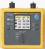
Power Logger Instrument Familiarity Description of the Control Elements Figure 2 indicates the control elements of the Power Logger. Activation - Adjustment of the background lighting Activating the appropriate cursor function Switching between measuring and recording function Stopping and continuing the measurement CURRENT INPUT MAX 30V HOLD RUN RECORD MEASURE CURSOR 1735 POWER LOGGER POWER HARMONICS SCOPE METER V A Hz OFF EVENTS 600V CAT VOLTAGE INPUT ENTER SAVE SCREEN ESC MENU Rotary switch for switching On and for selecting different measuring functions Call up the menu (at anytime) or go back to a higher menu level without saving changes Save a screen shot or to acknowledge changes of the menu Cursor Control Key, Principal function and operation are described below. For details see its functional description Figure 2. Control Elements edx005.eps Note The symbols occurring in this operating instruction 21 and 4 5 correspond to the respective directions of the cursor control keys. 9
-
 1
1 -
2
-
3
-
4
-
5
-
6
-
7
-
8
-
9
-
10
-
11
-
12
-
13
-
 14
14 -
 15
15 -
 16
16 -
 17
17 -
 18
18 -
 19
19 -
 20
20 -
 21
21 -
 22
22 -
 23
23 -
 24
24 -
25
-
26
-
27
-
28
-
29
-
30
-
31
-
32
-
33
-
34
-
35
-
36
-
37
-
38
-
39
-
40
-
41
-
42
-
43
-
44
-
45
-
46
-
47
-
48
-
49
-
50
-
51
-
52
-
53
-
54
-
55
-
56
-
57
-
58
-
59
-
60
-
61
-
62
-
63
-
64
-
65
-
66
-
67
-
68
-
69
-
70
-
71
-
72
-
73
-
74
-
75
-
76
-
77
-
78
-
79
-
80
-
81
-
82
 |
 |
