Fujitsu MHN2100AT Manual/User Guide - Page 128
Max. cylinder [MSB]/Max. LBA
 |
View all Fujitsu MHN2100AT manuals
Add to My Manuals
Save this manual to your list of manuals |
Page 128 highlights
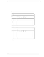
Interface At command completion (I/O registers contents to be read) 1F7 (ST) H 1F6H(DH) 1F5H(CH) 1F4H(CL) 1F3H(SN) 1F2 (SC) H 1F1 (ER) H Status information x x x DV Max head/LBA [MSB] Max. cylinder [MSB]/Max. LBA Max. cylinder [LSB]/Max. LBA Max. sector/Max. LBA [LSB] xx Error information (18) EXECUTE DEVICE DIAGNOSTIC (X'90') This command performs an internal diagnostic test (self-diagnosis) of the device. This command usually sets the DRV bit of the Drive/Head register is to 0 (however, the DV bit is not checked). If two devices are present, both devices execute self-diagnosis. If device 1 is present: • Both devices shall execute self-diagnosis. • The device 0 waits for up to 5 seconds until device 1 asserts the PDIAGsignal. • If the device 1 does not assert the PDIAG- signal but indicates an error, the device 0 shall append X'80' to its own diagnostic status. • The device 0 clears the BSY bit of the Status register and generates an interrupt. (The device 1 does not generate an interrupt.) • A diagnostic status of the device 0 is read by the host system. When a diagnostic failure of the device 1 is detected, the host system can read a status of the device 1 by setting the DV bit (selecting the device 1). When device 1 is not present: • The device 0 posts only the results of its own self-diagnosis. • The device 0 clears the BSY bit of the Status register, and generates an interrupt. Table 5.6 lists the diagnostic code written in the Error register which is 8-bit code. If the device 1 fails the self-diagnosis, the device 0 "ORs" X'80' with its own status and sets that code to the Error register. 5-52 C141-E120-02EN
-
 1
1 -
2
-
3
-
4
-
5
-
6
-
7
-
8
-
9
-
10
-
11
-
12
-
13
-
14
-
15
-
16
-
17
-
18
-
19
-
20
-
21
-
22
-
23
-
24
-
25
-
26
-
27
-
28
-
29
-
30
-
31
-
32
-
33
-
34
-
35
-
36
-
37
-
38
-
39
-
40
-
41
-
42
-
43
-
44
-
45
-
46
-
47
-
48
-
49
-
50
-
51
-
52
-
53
-
54
-
55
-
56
-
57
-
58
-
59
-
60
-
61
-
62
-
63
-
64
-
65
-
66
-
67
-
68
-
69
-
70
-
71
-
72
-
73
-
74
-
75
-
76
-
77
-
78
-
79
-
80
-
81
-
82
-
83
-
84
-
85
-
86
-
87
-
88
-
89
-
90
-
91
-
92
-
93
-
94
-
95
-
96
-
97
-
98
-
99
-
100
-
101
-
102
-
103
-
104
-
105
-
106
-
107
-
108
-
109
-
110
-
111
-
112
-
113
-
114
-
115
-
116
-
117
-
118
-
119
-
120
-
121
-
122
-
 123
123 -
 124
124 -
 125
125 -
 126
126 -
 127
127 -
 128
128 -
 129
129 -
 130
130 -
 131
131 -
 132
132 -
 133
133 -
134
-
135
-
136
-
137
-
138
-
139
-
140
-
141
-
142
-
143
-
144
-
145
-
146
-
147
-
148
-
149
-
150
-
151
-
152
-
153
-
154
-
155
-
156
-
157
-
158
-
159
-
160
-
161
-
162
-
163
-
164
-
165
-
166
-
167
-
168
-
169
-
170
-
171
-
172
-
173
-
174
-
175
-
176
-
177
-
178
-
179
-
180
-
181
-
182
-
183
-
184
-
185
-
186
-
187
-
188
-
189
-
190
-
191
-
192
-
193
-
194
-
195
-
196
-
197
-
198
-
199
-
200
-
201
-
202
-
203
-
204
-
205
-
206
-
207
-
208
-
209
-
210
-
211
-
212
-
213
-
214
-
215
-
216
-
217
-
218
-
219
-
220
-
221
-
222
-
223
-
224
-
225
-
226
-
227
-
228
-
229
-
230
-
231
-
232
-
233
-
234
-
235
-
236
 |
 |
