Fujitsu MHN2100AT Manual/User Guide - Page 73
Actuator motor control, Servo
 |
View all Fujitsu MHN2100AT manuals
Add to My Manuals
Save this manual to your list of manuals |
Page 73 highlights
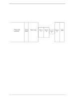
4.7 Servo Control (1) Write/read recovery This area is used to absorb the write/read transient and to stabilize the AGC. (2) Servo mark This area generates a timing for demodulating the gray code and positiondemodulating the servo A to D by detecting the servo mark. (3) Gray code (including index bit) This area is used as cylinder address. The data in this area is converted into the binary data by the gray code demodulation circuit (4) Servo A, servo B, servo C, servo D This area is used as position signals between tracks and the IDD control at ontrack so that servo A level equals to servo B level. (5) PAD This area is used as a gap between servo and data. 4.7.4 Actuator motor control The voice coil motor (VCM) is controlled by feeding back the servo data recorded on the data surface. The MPU fetches the position sense data on the servo frame at a constant interval of sampling time, executes calculation, and updates the VCM drive current. The servo control of the actuator includes the operation to move the head to the reference cylinder, the seek operation to move the head to the target cylinder to read or write data, and the track-following operation to position the head onto the target track. (1) Operation to move the head to the reference cylinder The MPU moves the head to the reference cylinder when the power is turned. The reference cylinder is in the data area. When power is applied the heads are moved from the inner circumference shunt zone to the normal servo data zone in the following sequence: a) Micro current is fed to the VCM to press the head against the outer circumference. b) The head is loaded on the disk. c) When the servo mark is detected the head is moved slowly toward the inner circumference at a constant speed. C141-E120-02EN 4-21
-
 1
1 -
2
-
3
-
4
-
5
-
6
-
7
-
8
-
9
-
10
-
11
-
12
-
13
-
14
-
15
-
16
-
17
-
18
-
19
-
20
-
21
-
22
-
23
-
24
-
25
-
26
-
27
-
28
-
29
-
30
-
31
-
32
-
33
-
34
-
35
-
36
-
37
-
38
-
39
-
40
-
41
-
42
-
43
-
44
-
45
-
46
-
47
-
48
-
49
-
50
-
51
-
52
-
53
-
54
-
55
-
56
-
57
-
58
-
59
-
60
-
61
-
62
-
63
-
64
-
65
-
66
-
67
-
 68
68 -
 69
69 -
 70
70 -
 71
71 -
 72
72 -
 73
73 -
 74
74 -
 75
75 -
 76
76 -
 77
77 -
 78
78 -
79
-
80
-
81
-
82
-
83
-
84
-
85
-
86
-
87
-
88
-
89
-
90
-
91
-
92
-
93
-
94
-
95
-
96
-
97
-
98
-
99
-
100
-
101
-
102
-
103
-
104
-
105
-
106
-
107
-
108
-
109
-
110
-
111
-
112
-
113
-
114
-
115
-
116
-
117
-
118
-
119
-
120
-
121
-
122
-
123
-
124
-
125
-
126
-
127
-
128
-
129
-
130
-
131
-
132
-
133
-
134
-
135
-
136
-
137
-
138
-
139
-
140
-
141
-
142
-
143
-
144
-
145
-
146
-
147
-
148
-
149
-
150
-
151
-
152
-
153
-
154
-
155
-
156
-
157
-
158
-
159
-
160
-
161
-
162
-
163
-
164
-
165
-
166
-
167
-
168
-
169
-
170
-
171
-
172
-
173
-
174
-
175
-
176
-
177
-
178
-
179
-
180
-
181
-
182
-
183
-
184
-
185
-
186
-
187
-
188
-
189
-
190
-
191
-
192
-
193
-
194
-
195
-
196
-
197
-
198
-
199
-
200
-
201
-
202
-
203
-
204
-
205
-
206
-
207
-
208
-
209
-
210
-
211
-
212
-
213
-
214
-
215
-
216
-
217
-
218
-
219
-
220
-
221
-
222
-
223
-
224
-
225
-
226
-
227
-
228
-
229
-
230
-
231
-
232
-
233
-
234
-
235
-
236
 |
 |
