Garmin GPSMAP 5212 Installation Instructions - Page 15
Wiring Additional NMEA 0183 Devices, Basic NMEA 0183 Wiring - installation
 |
UPC - 753759066109
View all Garmin GPSMAP 5212 manuals
Add to My Manuals
Save this manual to your list of manuals |
Page 15 highlights
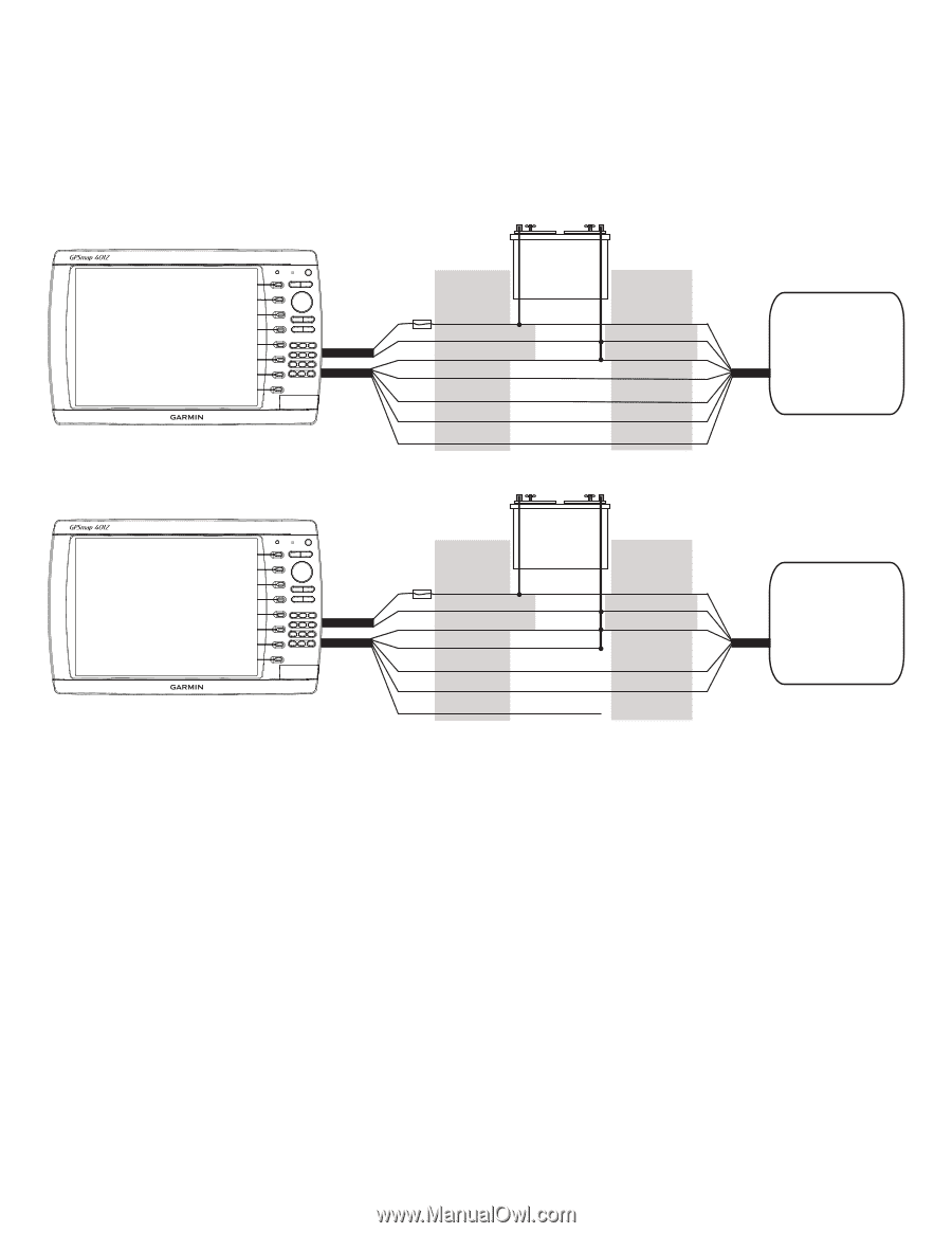
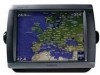
Wiring Additional NMEA 0183 Devices The NMEA 0183 data cable included with the GPSMAP 4000/5000 series chartplotter supports the NMEA 0183 standard, which is used to wire various NMEA 0183-compliant devices, such as VHF radios, NMEA instruments, autopilots, or a computer. Basic NMEA 0183 Wiring These diagrams illustrate basic NMEA 0183 wiring used to connect your GPSMAP 4000/5000 series chartplotter to NMEA 0183-compliant devices such as an AIS or DSC device. For more-complete information on the NMEA 0183 capabilities of the GPSMAP 4000/5000 series chartplotter, see the section on advanced NMEA 0183 wiring (page 16). Garmin GPSMAP 4000/5000 series chartplotter wire color + - BATTERY 10-35 Vdc Wire Power cable NMEA 0183 Cable > Fuse 7.5 A - 42 V Red (power) Black (pwr gnd) Black (data GND) White orange/white Red (power) Black (pwr gnd) Black (data GND) Transmit A(+) transmit B(-) > > > > Gray Receive A(+) > > pink receive B(-) > Wiring to a NMEA 0183-compliant Device (AIS) NMEA 0183-compliant device (AIS) Garmin GPSMAP 4000/5000 series chartplotter wire color + - BATTERY 10-35 Vdc Wire Power cable NMEA 0183 Cable > Fuse 7.5 A - 42 V Red (power) Black (pwr gnd) Black (data GND) orange/white white Red (power) Black (pwr gnd) Black (data GND) Transmit > > > gray > pink unconnected Receive > Wiring to a Single-ended NMEA 0183-compliant Device NMEA 0183-compliant device Notes: • If the NMEA 0183-compliant device has only one receiving wire (no A, B, +, or -), leave the pink wire unconnected. • If the NMEA 0183-compliant device has only one transmitting wire (no A, B, +, or -), connect the orange/white wire to ground. • Consult the installation instructions of your NMEA 0183-compliant device to identify the Transmit A(+) and B(-) wires and Receive A(+) and B(-) wires. • Use 28 AWG, shielded, twisted-pair wiring for extended runs of wire. • Solder all connections and seal the connection with heat-shrink tubing. GPSMAP 4000/5000 Series Installation Instructions 15
-
 1
1 -
2
-
3
-
4
-
5
-
6
-
7
-
8
-
9
-
 10
10 -
 11
11 -
 12
12 -
 13
13 -
 14
14 -
 15
15 -
 16
16 -
 17
17 -
 18
18 -
 19
19 -
 20
20 -
21
-
22
-
23
-
24
 |
 |