Garmin GPSMAP 5212 Installation Instructions - Page 18
Wiring to an Optional Alarm, Wiring to a DB-9 PC Serial Connector
 |
UPC - 753759066109
View all Garmin GPSMAP 5212 manuals
Add to My Manuals
Save this manual to your list of manuals |
Page 18 highlights
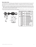
Wiring to an Optional Alarm The GPSMAP 4000/5000 series chartplotter can be used with a lamp, a horn, or both, to sound or flash an alert when the chartplotter displays a message. The alarm does not need to be wired for the GPSMAP 4000/5000 chartplotter to function. The alarm circuit switches to a low-voltage state when the alarm sounds. The maximum current is 100 mA, and a relay is needed to limit the current from the chartplotter to 100 mA. To select between visual and audible alerts, install a switch. Garmin GPSMAP 4000/5000 series chartplotter Power cable Wire Color Fuse 7.5 A - 42 V Red (power) Black (gnd) + Battery - 10-35 Vdc Horn NMEA 0183 Cable Yellow (alarm) Wiring to a lamp, a horn, or both. Relay 100 ma max coil current Lamp Wiring to a DB-9 PC Serial Connector The GPSMAP 4008/4208/4010/4210/4012/4212/5008/5208/5012/5212 chartplotters can be connected to a PC with a serial port by wiring the chartplotter to a DB-9 serial connector. Garmin GPSMAP 4000/5000 series chartplotter Power cable NMEA 0183 Cable Wire see table for Fuse wire colors 7.5 A - 42 V Red (power) + - Battery 10-35 Vdc Black (pwr gnd) Black (data GND) RX / B(-) > RX / A(+) > > tX / A(-) > TX / B(+) Unconnected Wiring to a DB-9 Serial PC Connector DB-9 pin numbers pin 5: gnd Pin 3: tX Pin 2: rX > > DB-9 Serial PC Connector 1 6 2 7 3 8 4 9 5 End View 18 GPSMAP 4000/5000 Series Installation Instructions
-
 1
1 -
2
-
3
-
4
-
5
-
6
-
7
-
8
-
9
-
10
-
11
-
12
-
 13
13 -
 14
14 -
 15
15 -
 16
16 -
 17
17 -
 18
18 -
 19
19 -
 20
20 -
 21
21 -
 22
22 -
 23
23 -
24
 |
 |
