Garmin GPSMAP 5212 Installation Instructions - Page 19
Marine Video Cable
 |
UPC - 753759066109
View all Garmin GPSMAP 5212 manuals
Add to My Manuals
Save this manual to your list of manuals |
Page 19 highlights
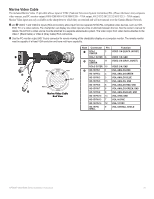
Marine Video Cable The included Marine Video 17-pin cable allows input of NTSC (National Television System Committee)/PAL (Phase Alternate Line) composite video sources, and PC monitor output (4008/4208/4010/4210/5008/5208 = VGA output, 4012/4212/5012/5212/5015/5215 = XGA output). Marine Video inputs are only available on the chartplotter to which they are attached and will not transmit over the Garmin Marine Network. ➊ and ➋ VIDEO 1 and VIDEO 2 Inputs (RCA connectors) allow input from two separate NTSC/PAL compatible video devices, such as VCR, DVD, TV, or a video camera. The chartplotter can display one video input at a time or alternate between the two. See the owner's manual for details. Sound from a video source must be attached to a separate stereo/audio system. The video output from video device attaches to the Video 1 (Black Cable) or Video 2 (Gray Cable) RCA connectors. ➌ Use the PC monitor output (HD 15-pin) connector for remote viewing of the chartplotter display on a computer monitor. The remote monitor must be capable of at least VGA resolution and have multi-sync capability. ➌ ➋ ➊ Pin 2 Pin 1 Pin 7 Pin 17 Marine Video Cable End View Note Connector Pin Function ➊ RCA-1 Center 2 Video 1 in (black jacket) RCA-1 Outer 6 Video 1 in, gnd ➋ RCA-2 Center 11 Video 2 in (gray jacket) RCA-2 Outer 15 Video 2 in, gnd ➌ HD-15 Pin 1 1 VGA, analog-red HD-15 Pin 2 4 VGA, analog-green HD-15 Pin 3 3 VGA, analog-blue HD-15 Pin 5 13 VGA, analog, gnd HD-15 Pin 6 8 VGA, analog-red, gnd HD-15 Pin 7 8 VGA, analog-green, gnd HD-15 Pin 8 8 VGA, analog-blue, gnd HD-15 Pin 10 13 VGA, sync-Gnd HD-15 Pin 13 7 VGA, H-sync HD-15 Pin 14 12 VGA, V-sync HD-15 Pin shell 9 VGA, overall shield GPSMAP 4000/5000 Series Installation Instructions 19
-
 1
1 -
2
-
3
-
4
-
5
-
6
-
7
-
8
-
9
-
10
-
11
-
12
-
13
-
 14
14 -
 15
15 -
 16
16 -
 17
17 -
 18
18 -
 19
19 -
 20
20 -
 21
21 -
 22
22 -
 23
23 -
 24
24
 |
 |
