Gateway DX4300 Gateway Desktop User's Guide - Page 16
Case cover Phillips
 |
View all Gateway DX4300 manuals
Add to My Manuals
Save this manual to your list of manuals |
Page 16 highlights
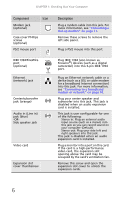
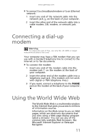
CHAPTER 1: Checking Out Your Computer Component Icon Modem jack (optional) Case cover Phillips screws (optional) PS/2 mouse port IEEE 1394/FireWire port (optional) Ethernet (network) jack Center/subwoofer jack (orange) Audio in (Line in) jack (blue) -ORSide speaker jack Video card Expansion slot cover thumbscrew Description Plug a modem cable into this jack. For more information, see "Connecting a dial-up modem" on page 11. Remove these screws to remove the left side panel. Plug a PS/2 mouse into this port. Plug IEEE 1394 (also known as Firewire®) devices (such as a digital camcorder) into this 6-pin IEEE 1394 port. Plug an Ethernet network cable or a device (such as a DSL or cable modem for a broadband Internet connection) into this jack. For more information, see "Connecting to a broadband modem or network" on page 10. Plug your center speaker and subwoofer into this jack. This jack is disabled when an audio expansion card is installed. This jack is user configurable for one of the following: ■ Stereo in: Plug an external audio input source (such as a stereo) into this jack so you can record sound on your computer (Default). ■ Stereo out: Plug your side left and right speakers into this jack. This jack is disabled when an audio expansion card is installed. Plug a monitor into a port on this card. If the card is a high-performance video card, the expansion slot opening above the card may be occupied by the card's ventilation fan. Remove this screw and open the expansion slot cover to unlock the expansion cards. 6
-
 1
1 -
2
-
3
-
4
-
5
-
6
-
7
-
8
-
9
-
10
-
 11
11 -
 12
12 -
 13
13 -
 14
14 -
 15
15 -
 16
16 -
 17
17 -
 18
18 -
 19
19 -
 20
20 -
 21
21 -
22
-
23
-
24
-
25
-
26
-
27
-
28
-
29
-
30
-
31
-
32
-
33
-
34
-
35
-
36
-
37
-
38
-
39
-
40
-
41
-
42
-
43
-
44
-
45
-
46
-
47
-
48
-
49
-
50
-
51
-
52
-
53
-
54
-
55
-
56
-
57
-
58
-
59
-
60
-
61
-
62
-
63
-
64
-
65
-
66
-
67
-
68
-
69
-
70
-
71
-
72
-
73
-
74
-
75
-
76
-
77
-
78
-
79
-
80
-
81
-
82
 |
 |
