Genie PowerLift Excelerator Owner's Manual - Page 17
Open Red Parts Bag
 |
View all Genie PowerLift Excelerator manuals
Add to My Manuals
Save this manual to your list of manuals |
Page 17 highlights
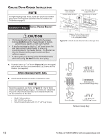
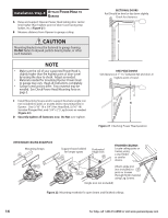
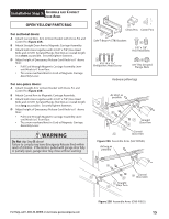
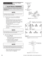
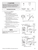
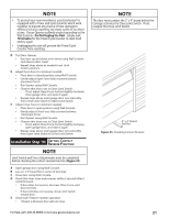
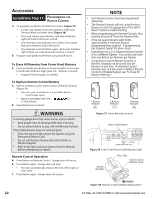
CAUTION Staples which are too tight may cut or pinch Wires. Cut or pinched Wires can cause the Safe-T-Beam® System to stop working. When installing the Insulated Staples, make sure you fasten them only as tightly as needed to hold the Wire securely. OPEN RED PARTS BAG C Install Safe-T-Beam® Wiring (Figure 27): • Route Wire and Insulated Staples (Figure 28 and Figure 29). - Securely fasten Wires with Insulated Staples as you go. Staples should be snug only. - Wires between garage wall and Power Head should be run on top of Rail and underneath Wire Clips. • Attach Wires to Safe-T-Beam® Sensors. - Split and strip Wire ends to be connected as shown. - Loosen Terminal Screws. - Insert each Wire under flat plate and tighten Screw. It does not matter which Wire, white or striped, goes on which Terminal. • Attach Wires at Power Head. - Wires are connected to Terminals #2 and #3 on Power Head Terminal Block. It does not matter which Wire, white or striped, goes on which Terminal. • Check the following. - Ensure that no part of door or its hardware is in path between Source or Sensor Lenses. • Ensure that tops of Lenses are between 5" - 6" above floor. Brackets are flexible and can be adjusted slightly if needed. NOTE The Safe-T-Beam® alignment check will be performed following connection to electrical power. Do Not plug in yet! Insulated Staples #6-11/4" (approximately Pan Head 30 parts) Screws Hardware (red bag) Wall Button Wire Approx. 11/2" Strip approx. 1/2" Figure 27 Wire the Safe-T-Beam® System Wire Clips Insulated Staples Terminal attachments at Safe-T-Beam® Allow slack for adjustment Terminal attachments at Power Head Figure 28 Wiring Method A Wire Clips Insulated Staples For Help, call 1-800-35-GENIE or visit www.geniecompany.com Terminal attachments at Safe-T-Beam® Allow slack for adjustment Terminal attachments at Power Head Figure 29 Wiring Method B 17
-
 1
1 -
2
-
3
-
4
-
5
-
6
-
7
-
8
-
9
-
10
-
11
-
 12
12 -
 13
13 -
 14
14 -
 15
15 -
 16
16 -
 17
17 -
 18
18 -
 19
19 -
 20
20 -
 21
21 -
 22
22 -
23
-
24
-
25
-
26
-
27
-
28
-
29
-
30
 |
 |
