Genie PowerLift Excelerator Owner's Manual - Page 7
Parts List - screw drive
 |
View all Genie PowerLift Excelerator manuals
Add to My Manuals
Save this manual to your list of manuals |
Page 7 highlights
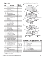
Parts List Item Part Name Item Part Name 1 Power Head Assembly (main carton) Quantity Required 1-Pc Rail 3-Pc Rail 1 1 Power Head Assembly Exploded View [1] 2 3 4 4A 4B 4C 8 9 10 11 12 13 14 15 16 18 19 21 22 23 24 25 26 28 30 31 32 33 34 35 36 37* 38* 40* 41* 42* 43* 44* 45* 46 47* 48* 49* 50* 51* 52* 53 54 55* 56 57 58 1/4"-20 x 13/16" Hex Head Shoulder Bolt (blue bag) (yellow shoulder bolt) 2 2 Rail Assembly, 1 piece (separate carton) 1 Rail Assembly, 3 piece (main carton) 1 First Rail Section (main carton) 1 Middle Rail Section (main carton) 1 End Rail Section (main carton) 1 1/4"-20 Hex Serrated Flange Nut (blue bag) 4 4 Rail Clamps (main carton) 4 5/16"-18 x 11/16" Hex Head Shoulder Bolt (blue bag) va ries/mo del 8 5/16"-18 Hex Serrated Flange Nut (blue & orange bags) 12 Magnetic Carriage Assembly (main carton) 1 1 Collar (blue bag) 3 Retaining Clip (blue bag) 3 Rail Strap (blue bag) 1 1 1/4"-20 Hex Head Bolt (blue bag) 2 2 Open Limit Switch Assembly (White)(green bag) 1 1 Close Limit Switch Assembly (Brown) (green bag) 1 1 # 8-32 x 1" Hex Head Screw (green bag) 2 2 Emergency Release Cord (carriage) 1 1 Emergency Release Cord (main carton) 10' & 12' only Emergency Release Knob (green bag) 1 1 Emergency Release Tag (carriage) 1 1 Header Bracket (orange bag) 1 1 Door Bracket (orange bag) varies1/m ode l 1 1/4" x 2" Lag Screw (orange bag) 8 Straight Door Arm (main carton) 1 1 Clevis Pin, 3/8" x 15/16" (yellow bag) 2 2 Cotter Pin, .073" dia. (yellow bag) 2 2 Curved Door Arm (main carton) 1 1 3/8" x 7/8" Hex Head Bolt (yellow bag) 2 2 3/8" Hex Serrated Flange Nut (yellow bag) 2 2 2-Conductor Wire (main carton) 1 Roll 1 Roll Insulated Staple (red bag) approx. 30 approx. 30 Wall Console (main carton) 1 1 # 6 x 1-1/4" Pan Head Screw (red bag) 2 2 Entrapment Warning Label (manual)(main carton) 1 1 Safe-T-Beam Sensor (Green LED)(main carton) 1 1 Safe-T-Beam Source (Red LED)(main carton) 1 1 Safe-T-Beam Bracket (yellow bag) 2 2 Coupler (blue bag) 1 1 #10 x1 1/4" Phillips Hex Head Screw (yellow bag) 4 4 One Button Remote Control (main carton) varies/model varies/model Three Button Remote Control (main carton) varies/model varies/model Wireless Keypad (main carton) varies/model varies/model Two Button Remote Control (main carton) varies/model varies/model Safety & Maintenance Guide (manual)(main carton) 1 1 Wire Clip (green bag) v aries/model 7 Carriage Stop 1 1 5/16"-18 x 3/4" Hex Head Bolt (orange bag) 3 1/4-20 x 3/4" Self-drilling Screw (orange bag) 3 3 Mounting Straps (main carton) 2 2 Wall Button (red bag) 1 1 * Denotes items not shown on page 8. These items will be illustrated throughout the manual as required. Model Number Serial Number POWER HEAD ASSEMBLY PARTS LIST Item 1A 1B 1C 1D 1E 1G 1H 1K 1L 1M 1P Part Name Lens Top Plate Assembly Light Socket (2) Motor Assembly Cover Motor Drive Board Controller Board # 10-24 x 3/8" Hex Head # 8-32 x 1" Phillips Screw # 8-32 x 3/8" Slotted Hex Head Screw Power Cord For Help, call 1-800-35-GENIE or visit www.geniecompany.com 7
-
 1
1 -
 2
2 -
 3
3 -
 4
4 -
 5
5 -
 6
6 -
 7
7 -
 8
8 -
 9
9 -
 10
10 -
 11
11 -
 12
12 -
13
-
14
-
15
-
16
-
17
-
18
-
19
-
20
-
21
-
22
-
23
-
24
-
25
-
26
-
27
-
28
-
29
-
30
 |
 |
