Gigabyte G1.Assassin Manual - Page 21
Installing the 5.25 Front Access Control Panel - overclocking
 |
UPC - 818313012203
View all Gigabyte G1.Assassin manuals
Add to My Manuals
Save this manual to your list of manuals |
Page 21 highlights
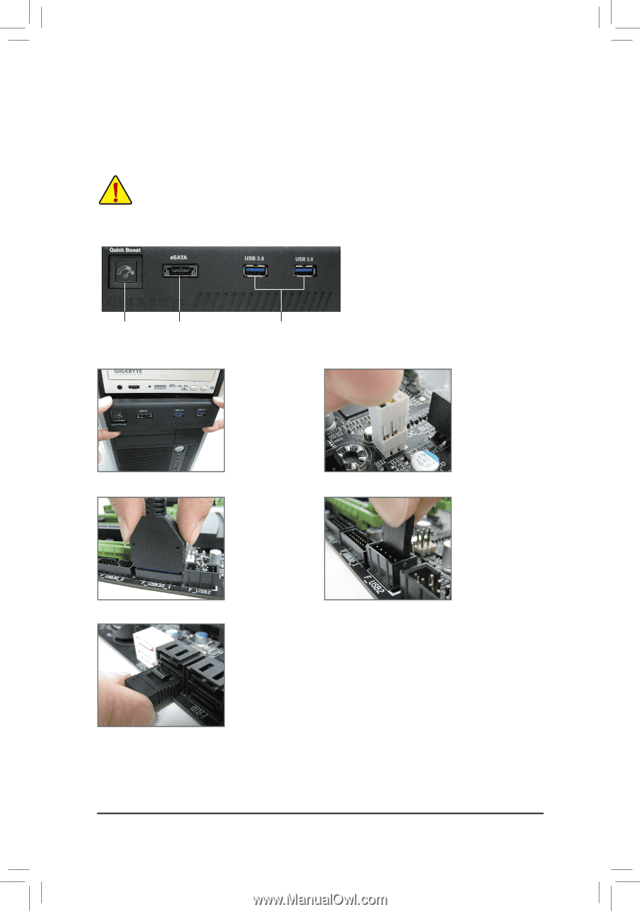
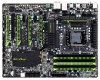
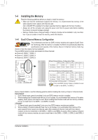
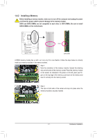
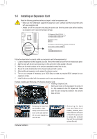
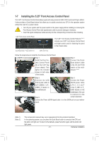
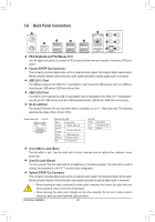
1-7 Installing the 5.25" Front Access Control Panel The 5.25" Front Access Control Panel allows quick and easy access to USB 3.0/2.0 ports and Power eSATA. It also provides a Quick Boost button that allows you to quickly overclock your CPU in the operation system without the need for a system reboot. • Turn off your system and the power switch on the power supply before installing or removing the Front Access Control Panel and signal/power cable to prevent damage to hardware. • Insert the signal cable/power cable securely into the corresponding connectors when installing. 5.25" Front Access Control Panel The 5.25" Front Access Control Panel kit (Note 1) includes one 5.25" Front Access Control Panel and eight screws used for fastening the panel to the chassis sides. Quick Boost Button Power eSATA Port USB 3.0/2.0 Ports Follow the steps below to install the Front Access Control Panel: Step 1: Install the Front Access Control Panel into a free 5.25" bay of your chassis. Then tighten the included screws to both sides of the chassis. Step 2: Connect the Quick Boost button's cable to the OC_BUTTON header on the motherboard. (Note 2) Step 3: Step 4: Connect the USB Connect the Power 3.0/2.0 ports' cable to eSATA power cable the F_USB30_1 or F_ to Pin 1, 3, 5, and 7 USB30_2 header on of the F_USB1 or F_ the motherboard. USB2 header on the motherboard. Be sure to connect it in the Step 5: correct orientation. Connect the Power eSATA signal cable to a free SATA port on your mother- board. (Note 1) (Note 2) The components received may vary in appearance from the products illustrated. In the operating system, you can press the Quick Boost button to overclock the CPU and the button will light red. To return to the defaults, press the button again and the button will light green. - 21 - Hardware Installation
-
 1
1 -
2
-
3
-
4
-
5
-
6
-
7
-
8
-
9
-
10
-
11
-
12
-
13
-
14
-
15
-
 16
16 -
 17
17 -
 18
18 -
 19
19 -
 20
20 -
 21
21 -
 22
22 -
 23
23 -
 24
24 -
 25
25 -
 26
26 -
27
-
28
-
29
-
30
-
31
-
32
-
33
-
34
-
35
-
36
-
37
-
38
-
39
-
40
-
41
-
42
-
43
-
44
-
45
-
46
-
47
-
48
-
49
-
50
-
51
-
52
-
53
-
54
-
55
-
56
-
57
-
58
-
59
-
60
-
61
-
62
-
63
-
64
-
65
-
66
-
67
-
68
-
69
-
70
-
71
-
72
-
73
-
74
-
75
-
76
-
77
-
78
-
79
-
80
-
81
-
82
-
83
-
84
-
85
-
86
-
87
-
88
-
89
-
90
-
91
-
92
-
93
-
94
-
95
-
96
-
97
-
98
-
99
-
100
-
101
-
102
-
103
-
104
-
105
-
106
-
107
-
108
-
109
-
110
-
111
-
112
-
113
-
114
-
115
-
116
-
117
-
118
-
119
-
120
-
121
-
122
-
123
-
124
-
125
-
126
-
127
-
128
 |
 |