Gigabyte GA-6JIEV2-RH Manual
Gigabyte GA-6JIEV2-RH Manual
 |
View all Gigabyte GA-6JIEV2-RH manuals
Add to My Manuals
Save this manual to your list of manuals |
Gigabyte GA-6JIEV2-RH manual content summary:
- Gigabyte GA-6JIEV2-RH | Manual - Page 1
GA-6JIEV2-RH Intel® mini-ITX Motherboard USER'S MANUAL Intel® mini-ITX Motherboard Rev. 1001 * The WEEE marking on the product indicates this product must not be disposed of with user's other household waste - Gigabyte GA-6JIEV2-RH | Manual - Page 2
: For detailed product information and specifications, please carefully read the "Product User Manual". For detailed information related to Gigabyte's unique features, please go to "Technology Guide" section on Gigabyte's website to read or download the information you need. For more product - Gigabyte GA-6JIEV2-RH | Manual - Page 3
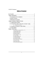
GA-6JIEV2-RH Motherboard Table of Content Item Checklist 4 Chapter 1Introduction 5 1-1Considerations Prior to Installation 5 1.2Features Summary 6 1.3Motherboard Components 8 Chapter 2Hardware Installation Process 9 2-1: Installing Memory Module 9 2-2: Connect ribbon - Gigabyte GA-6JIEV2-RH | Manual - Page 4
Item Checklist The GA-6JIEV2-RH motherboard I/O Shield Kit CD for motherboard driver & utility GA-6JIEV2-RH Quick Reference Guide Power cable x 1 B4P/S4P Cable x 1 Optional Power Adapter x 1 Introduction * The items listed above are for reference only, and are subject to change - Gigabyte GA-6JIEV2-RH | Manual - Page 5
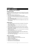
GA-6JIEV2-RH installation, please follow the instructions below: 1. Please turn off the information in the provided manual. 3. Before using the about any installation steps or have a problem related to the use of the product, the conditions recommended in the user manual. 3. Damage due to improper - Gigabyte GA-6JIEV2-RH | Manual - Page 6
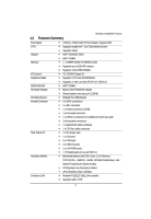
170mm x 170mm Mini ITX form factor, 8 layers PCB. Supports single Intel® ULV CeleronM processor Supports 1GHz Intel® 910GMLE MCH Intel® ICH6M 1 x DDR2 DIMM SO-DIMM socket Supports up to 2GB 400 memory Supports 1.8V DDR2 DIMMs ITE IT8781F Super I/O Supports 1 PCI slot 32-Bit/33MHz - Gigabyte GA-6JIEV2-RH | Manual - Page 7
GA-6JIEV2-RH Motherboard BIOS Additional Features AWARD BIOS on 4Mb Flash ROM External Modem wake up Supports S1, S3, S4, S5 under Windows Operating System Wake on LAN (WOL) Supports Console Redirection Supports 3-pin Fan controller 7 - Gigabyte GA-6JIEV2-RH | Manual - Page 8
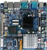
1.3 Motherboard Components AUDIO1 USB USB_LAN1 COM2 Introduction VGA COM DC Power KB_MS1 Jack GPIO connector F_USB1 Relteak ALC883 LVDS_CTL1 LVDS_CTL2 SJ1 SJ2 BIOS Intel ICH6M IDE1 Mini PCI-E ITE IT8781F COM4 LPT1 BAT1 SATA1 SATA2 Realtek RTL8111C Intel 910GMLE CPU F_PANEL1 DDR1 - Gigabyte GA-6JIEV2-RH | Manual - Page 9
6JIEV2-RH Motherboard Chapter 2 Hardware Installation Process 2-1: Installing Memory Module Before installing the memory modules, please comply with the following conditions: 1. Please make sure the computer power is switched off before installing or removing memory modules. The motherboard supports - Gigabyte GA-6JIEV2-RH | Manual - Page 10
Hardware Installation Process 2-2: Connect ribbon cables, cabinet wires, and power supply 2-2-1 : I/O Back Panel Introduction 10 - Gigabyte GA-6JIEV2-RH | Manual - Page 11
GA-6JIEV2-RH Motherboard DC Power Jack Connect the DC power to this port. PS/2 Keyboard zip, speaker...etc. have a standard USB interface. Also make sure your OS supports USB controller. If your OS does not support USB controller, please contact OS vendor for possible patch or driver updated. For - Gigabyte GA-6JIEV2-RH | Manual - Page 12
LAN LED Description LED2 (Green/Yellow) Hardware Installation Process LED1 (Green) Name LED1 LED2 Color Green Green Green Green Yellow Yellow Condition ON BLINK OFF OFF OFF ON BLINK ON BLINK Description LAN Link / no Access LAN Access Idle 10Mbps connection Port identification with 10 Mbps - Gigabyte GA-6JIEV2-RH | Manual - Page 13
GA-6JIEV2-RH Motherboard 2-3: Connectors Introduction & Jumper Setting 6 79 11 12 13 10 14 8 21 16 23 22 5 3 15 1 20 17 4 18 2 19 1. IDE1 (IDE cable connector) 2. SATA1 ( - Gigabyte GA-6JIEV2-RH | Manual - Page 14
two IDE devices, please set the jumper on one IDE device as Master and the other as Slave (for information, please refer to the instructions located on the IDE device). Before attaching the IDE cable, please take note of the foolproof groove in IDE connector. 2 44 1 43 2/3 ) SATA 1/2 (Serial - Gigabyte GA-6JIEV2-RH | Manual - Page 15
GA-6JIEV2-RH Motherboard 4 ) COM4 2 10 19 Pin No. 1 2 3 4 5 6 7 8 9 10 Definition DCDSIN2 SOUT2 DTR2GND DSR2RTS2CTS2RI2NC 5 ) F_USB1 (Front USB cable connector) Be careful with the polarity of the front - Gigabyte GA-6JIEV2-RH | Manual - Page 16
on the cable is the same as the pin assigment on the MB header. To find out if the chassis you are buying support front audio connector, please contact your dealer. Pin No. Definition 1 MIC_L 2 10 2 3 GND MIC_R 4 -ACZ_DEC 5 Line_R 19 6 GND 7 Faudio_JD 8 No Pin 9 Line_L 10 - Gigabyte GA-6JIEV2-RH | Manual - Page 17
GA-6JIEV2-RH Motherboard 9/10 ) SJ1/SJ2 (LVDS connectors) LVDS stands for Low-voltage differential signaling, which uses high-speed analog circuit techniques to provide multigigabit data transfers - Gigabyte GA-6JIEV2-RH | Manual - Page 18
11 ) LVDS_PSEL1 (Panel power selection connector) Connector Introduction 26 15 Pin No. 1 2 3 4 5 6 Definition P5V P5V LVDS2_VCC LVDS1_VCC P3V3 P3V3 12/13/14/15 ) RI_S2/RI_S3/RI_S5/RI_S4 (COM2/COM3/COM1/COM4 Ring In selection connectors) 26 RI_S2 RI_S3 RI_S5 15 RI_S2 RI_S3 Pin No. 1 2 3 4 - Gigabyte GA-6JIEV2-RH | Manual - Page 19
GA-6JIEV2-RH Motherboard 16 ) CPU_FAN1 (CPU fan cable connector) The cooler fan power connector supplies are designed with color-coded power connector wires. A red power connector wire indicates a positive connection and requires a +12V power voltage. The black connector wire is the ground wire - Gigabyte GA-6JIEV2-RH | Manual - Page 20
18 ) LPT1 (Parallel port connector) Connector Introduction 26 25 21 Pin No. 1 3 5 7 9 11 13 15 17 19 21 23 25 Definition STB# PTD0 PTD1 PTD2 PTD3 PTD4 PTD5 PTD6 PTD7 ACKBUSY PE SLCT Pin No. 2 4 6 8 10 12 14 16 18 20 22 24 26 Definition AFDERRINITSLINGND GND GND GND GND GND GND GND NC 20 - Gigabyte GA-6JIEV2-RH | Manual - Page 21
GA-6JIEV2-RH Motherboard 19 ) F_Panel (2X10 Pins Front Panel connector) Please connect the power LED, PC speaker, reset switch and power switch of your chassis front panel - Gigabyte GA-6JIEV2-RH | Manual - Page 22
is incorrectly replaced. Replace only with the same or equivalent type recommended by the manufacturer. Dispose of used batteries according to the manufacturer's instructions. If you want to erase CMOS... 1.Turn OFF the computer and unplug the power cord. 2.Remove the battery, wait for 30 second - Gigabyte GA-6JIEV2-RH | Manual - Page 23
GA-6JIEV2-RH Motherboard 22 ) CF_S1 (CF Mater/Slave Selction jumper) 1 1-2 Close: Slave. (Default setting) 1 2-3 Close: Mater. 23 ) CLR_CMOS1 (Clear CMOS Function) You may clear the CMOS data - Gigabyte GA-6JIEV2-RH | Manual - Page 24
2-4: Block Diagram Block Diagram VGA connector 48 BIT LVDS USB 2.0 From ICH6-M USB2 USB3 36 BIT LVDS CHRONTEL CH7308 USB 2.0 From ICH6-M RJ45 USB2 USB3 LAN Realtek RTL8111C CPU Intel Celeron-M CPU CLK Host Bus NB Intel 82910GMLE CHA Clock Generator Cypress CY28416OXC Clock Buffer - Gigabyte GA-6JIEV2-RH | Manual - Page 25
GA-6JIEV2-RH Motherboard Chapter 3 BIOS Setup BIOS (Basic Input and Output System) the BIOS setup screen by pressing "Ctrl + F1". If you wish to upgrade to a new BIOS, or GIGABYTE's Q-Flash utilitycan be used. Q-Flash allows the user to quickly and easily update or backup BIOS without entering the - Gigabyte GA-6JIEV2-RH | Manual - Page 26
The Main Menu (For example: BIOS Ver. : F1) BIOS Setup Once you enter Award BIOS CMOS Setup Utility, the Main Menu (as figure below) will appear on the screen. Use arrow keys to select among the items and press to accept or enter the sub-menu. CMOS Setup Utility-Copyright (C) 1984-2006 - Gigabyte GA-6JIEV2-RH | Manual - Page 27
GA-6JIEV2-RH Motherboard Standard CMOS Features This setup page includes all the items in standard compatible BIOS. Advanced BIOS Features This setup page includes all the items - Gigabyte GA-6JIEV2-RH | Manual - Page 28
this if no IDE/SATA devices are used and the system will skip the automatic detection step and allow for faster system start up. • Manual User can manually input the correct settings. Access Mode Use this to set the access mode for the hard drive. The four options are: CHS/LBA/Large - Gigabyte GA-6JIEV2-RH | Manual - Page 29
GA-6JIEV2-RH Motherboard Access Mode Use this to set the access mode for the hard drive. The two options are: Large/Auto(default:Auto) Capacity Capacity of - Gigabyte GA-6JIEV2-RH | Manual - Page 30
3-2 Advanced BIOS Features BIOS Setup CMOS Setup Utility-Copyright (C) 1984-2006 Award Software Advanced BIOS Features Hard Disk Boot Priority First Boot Device [Press Enter] [Floppy] Item Help Menu Level Second Boot Device Third Boot Device Password Check Limit CPUID Max. to 3 Init Display - Gigabyte GA-6JIEV2-RH | Manual - Page 31
GA-6JIEV2-RH Motherboard Init Display First This feature allows you to select the first initation of the monitor display from which card, when 8MB Set on-chip frame buffer size to 8 MB. (Default setting) (Note) This item will show up when you install a processor which supports this function. 31 - Gigabyte GA-6JIEV2-RH | Manual - Page 32
use; 4 for SATA and the other for PATA. Non-Combined Set On-Chip SATA mode to Non-Combined, SATA will be simulated to PATA mode. Support a maximum of 4 SATA devices. PATA devices will be ignored. PATA IDE Set to Ch.0 Master/Slave Set PATA IDE to Ch. 0 Master/Slave. (Default setting - Gigabyte GA-6JIEV2-RH | Manual - Page 33
GA-6JIEV2-RH Motherboard Disabled Disable USB 2.0 controller. Legacy USB storage detect This Port Mode This feature allows you to connect with an advanced printer via the port mode it supports. SPP Using Parallel port as Standard Parallel Port. (Default setting) EPP Using Parallel port as - Gigabyte GA-6JIEV2-RH | Manual - Page 34
3-4 Power Management Setup BIOS Setup CMOS Setup Utility-Copyright (C) 1984-2006 Award Software Power Management Setup ACPI Suspend Type Soft-Off by PWR-BTTN AC Back Function Resume by Alarm x Date (of Month) Alarm x Time (hh:mm:ss) Alarm [S3(STR)] [Instant-Off] [Memory] [Disabled] Everyday 0 : - Gigabyte GA-6JIEV2-RH | Manual - Page 35
GA-6JIEV2-RH Motherboard 3-5 PC Health Status CMOS Setup Utility-Copyright (C) 1984-2006 Award Software PC Health Status Case Instrusion Function Reset Case Open Status Case Opened Vcore - Gigabyte GA-6JIEV2-RH | Manual - Page 36
users only. Spread Spectrum Disabled Disable Spread Spectrum. Enabled Enable Spread Spectrum. (Default setting) (Note) This item will show up when you install a processor which supports this function. 36 - Gigabyte GA-6JIEV2-RH | Manual - Page 37
GA-6JIEV2-RH Motherboard 3-7 Load Fail-Safe Defaults CMOS Setup Utility-Copyright (C) 1984-2006 Award Software Standard CMOS Features Advanced BIOS Features Integrated Peripherals Power Management Setup PnP/ - Gigabyte GA-6JIEV2-RH | Manual - Page 38
GA-6JIEV2-RH Motherboard 3-9 Set Supervisor/User Password CMOS Setup Utility-Copyright (C) 1984-2006 Award Software Standard CMOS Features Advanced BIOS Features Integrated Peripherals Power Management Setup PnP/ - Gigabyte GA-6JIEV2-RH | Manual - Page 39
3-10 Save & Exit Setup BIOS Setup Standard CMOS Features Advanced BIOS Features Integrated Peripherals Power Management Setup PnP/PCI Configurations PC Health Status Frequency/Voltage Control ESC: Quit F8: Q-Flash Load Fail-Safe Defaults Load Optimized Defaults Set Supervisor - Gigabyte GA-6JIEV2-RH | Manual - Page 40
GA-6JIEV2-RH Motherboard 3- below before using Q-Flash to update BIOS: 1. From GIGABYTE's website, download the latest compressed BIOS update file that 6jiev.f1) to your floppy disk or hard disk. Note: Q-Flash only supports hard disks or flash drives using FAT32/16/12 file system. 3. Restart the - Gigabyte GA-6JIEV2-RH | Manual - Page 41
c. Select the BIOS file and press ENTER. Make sure again the BIOS file matches your motherboard model. BIOS Setup Step 2: The process of system reading the BIOS file from the floppy disk is displayed on the screen. When the message "Are you sure to update BIOS?" appears, press ENTER. The BIOS
-
 1
1 -
 2
2 -
 3
3 -
 4
4 -
 5
5 -
 6
6 -
 7
7 -
8
-
9
-
10
-
11
-
12
-
13
-
14
-
15
-
16
-
17
-
18
-
19
-
20
-
21
-
22
-
23
-
24
-
25
-
26
-
27
-
28
-
29
-
30
-
31
-
32
-
33
-
34
-
35
-
36
-
37
-
38
-
39
-
40
-
41
 |
 |

USER’S MANUAL
GA-6JIEV2-RH
Intel
®
mini-ITX Motherboard
Intel
®
mini-ITX Motherboard
Rev. 1001
*
The WEEE marking on the product indicates this product must not be disposed of with
user's other household waste and must be handed over to a designated collection point
for the recycling of waste electrical and electronic equipment!!
*
The WEEE marking applies only in European Union's member states.