Gigabyte GA-6JIEV2-RH Manual - Page 16
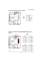
F_AUDIO1 Front AUDIO connector, 8 LVDS_CTL1/LVDS_CTL2 LVDS panel control connectors
 |
View all Gigabyte GA-6JIEV2-RH manuals
Add to My Manuals
Save this manual to your list of manuals |
Page 16 highlights
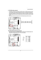
Connector Introduction 6 ) F_AUDIO1 (Front AUDIO connector) If you want to use Front Audio connector, you must remove 5-6, 9-10 Jumper. In order to utilize the front audio header, your chassis must have front audio connector. Also please make sure the pin assigment on the cable is the same as the pin assigment on the MB header. To find out if the chassis you are buying support front audio connector, please contact your dealer. Pin No. Definition 1 MIC_L 2 10 2 3 GND MIC_R 4 -ACZ_DEC 5 Line_R 19 6 GND 7 Faudio_JD 8 No Pin 9 Line_L 10 GND 7/8 )LVDS_CTL1/LVDS_CTL2 (LVDS panel control connectors) LVDS_CTL1 1 Pin No. Definition 1 LBKLT_EN 2 GND 3 NC 6 4 PANEL_BKLT 5 PANEL_BKLT 6 P5V LVDS_CTL2 16
-
 1
1 -
2
-
3
-
4
-
5
-
6
-
7
-
8
-
9
-
10
-
 11
11 -
 12
12 -
 13
13 -
 14
14 -
 15
15 -
 16
16 -
 17
17 -
 18
18 -
 19
19 -
 20
20 -
 21
21 -
22
-
23
-
24
-
25
-
26
-
27
-
28
-
29
-
30
-
31
-
32
-
33
-
34
-
35
-
36
-
37
-
38
-
39
-
40
-
41
 |
 |

16
Connector Introduction
6 )
F_AUDIO1 (Front AUDIO connector)
If you want to use Front Audio connector, you must remove 5-6, 9-10 Jumper. In order to utilize the
front audio header, your chassis must have front audio connector. Also please make sure the pin
assigment on the cable is the same as the pin assigment on the MB header. To find out if the chassis
you are buying support front audio connector, please contact your dealer.
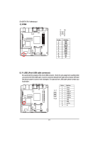
7/8 )LVDS_CTL1/LVDS_CTL2 (LVDS panel control connectors)
LVDS_CTL1
LVDS_CTL2
Pin No.
Definition
1
LBKLT_EN
2
GND
3
NC
4
PANEL_BKLT
5
PANEL_BKLT
6
P5V
1
6
2
9
1
10
Pin No.
Definition
1
MIC_L
2
GND
3
MIC_R
4
-ACZ_DEC
5
Line_R
6
GND
7
Faudio_JD
8
No Pin
9
Line_L
10
GND