Gigabyte GA-6JIEV2-RH Manual - Page 13
: Connectors Introduction & Jumper Setting
 |
View all Gigabyte GA-6JIEV2-RH manuals
Add to My Manuals
Save this manual to your list of manuals |
Page 13 highlights
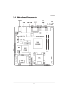
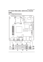
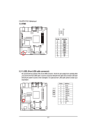
GA-6JIEV2-RH Motherboard 2-3: Connectors Introduction & Jumper Setting 6 79 11 12 13 10 14 8 21 16 23 22 5 3 15 1 20 17 4 18 2 19 1. IDE1 (IDE cable connector) 2. SATA1 (SATA cable connector) 3. SATA2 (SATA cable connector) 4. COM4 5. F_USB1 (Fornt USB cable connector) 6. F_AUDIO1 7. LVDS_CTL1 8. LVDS_CTL2 9. SJ1 10. SJ2 11. LVDS_PSEL1 12. RI_S2 13. RI_S3 14. RI_S5 15. RI_S4 16. CPU_FAN1 17. PWR1 18. LPT1 19. F_PANEL1 (Front panel connector) 20. BAT1 21. GPIO1 22. CF_S1 23. CLR_CMOS 13
-
 1
1 -
2
-
3
-
4
-
5
-
6
-
7
-
 8
8 -
 9
9 -
 10
10 -
 11
11 -
 12
12 -
 13
13 -
 14
14 -
 15
15 -
 16
16 -
 17
17 -
 18
18 -
19
-
20
-
21
-
22
-
23
-
24
-
25
-
26
-
27
-
28
-
29
-
30
-
31
-
32
-
33
-
34
-
35
-
36
-
37
-
38
-
39
-
40
-
41
 |
 |

13
GA-6JIEV2-RH
Motherboard
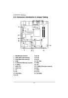
2-3: Connectors Introduction & Jumper Setting
1.
IDE1 (IDE cable connector)
2.
SATA1 (SATA cable connector)
3.
SATA2 (SATA cable connector)
4.
COM4
5.
F_USB1 (Fornt USB cable connector)
6.
F_AUDIO1
7.
LVDS_CTL1
8.
LVDS_CTL2
9.
SJ1
10. SJ2
11. LVDS_PSEL1
12. RI_S2
13. RI_S3
14. RI_S5
15. RI_S4
16. CPU_FAN1
17. PWR1
18. LPT1
19.
F_PANEL1 (Front panel connector)
20. BAT1
21. GPIO1
22. CF_S1
23. CLR_CMOS
9
10
8
11
7
12 13
14
4
5
6
1
2
3
15
16
17
18
19
20
21
22
23