Gigabyte GA-7VTXH User Manual - Page 13
Step1-2: CPU Installation, Socket, Actuation Lever
 |
View all Gigabyte GA-7VTXH manuals
Add to My Manuals
Save this manual to your list of manuals |
Page 13 highlights
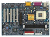
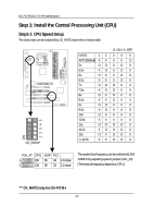
Step1-2: CPU Installation Hardware Installation Process CPU Top View Socket Actuation Lever CPU Bottom View Pin1 indicator 1. Pull up the CPU socket level and up to 90-degree angle. 2. Locate Pin 1 in the socket and look for a (golden) cut edge on the CPU upper corner. Then insert the CPU into the socket. Please make sure the CPU type is supported by the motherboard. If you do not match the CPU socket Pin 1 and CPU cut edge well, it will cause improper installation. Please change the insert orientation. 13
-
 1
1 -
2
-
3
-
4
-
5
-
6
-
7
-
 8
8 -
 9
9 -
 10
10 -
 11
11 -
 12
12 -
 13
13 -
 14
14 -
 15
15 -
 16
16 -
 17
17 -
 18
18 -
19
-
20
-
21
-
22
-
23
-
24
-
25
-
26
-
27
-
28
-
29
-
30
-
31
-
32
-
33
-
34
-
35
-
36
-
37
-
38
-
39
-
40
-
41
-
42
-
43
-
44
-
45
-
46
-
47
-
48
-
49
-
50
-
51
-
52
-
53
-
54
-
55
-
56
-
57
-
58
-
59
-
60
-
61
-
62
-
63
-
64
-
65
-
66
-
67
-
68
-
69
-
70
-
71
-
72
-
73
-
74
-
75
-
76
-
77
-
78
-
79
-
80
-
81
-
82
-
83
-
84
-
85
-
86
-
87
-
88
-
89
-
90
-
91
-
92
 |
 |

13
Hardware Installation Process
Step1-2: CPU Installation
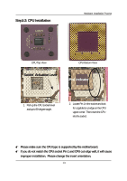
CPU Top View
CPU Bottom View
Socket
Actuation Lever
1.
Pull up the CPU socket level
and up to 90-degree angle.
Pin1 indicator
2.
Locate Pin 1 in the socket and look
for a (golden) cut edge on the CPU
upper corner. Then insert the CPU
into the socket.
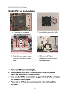
±
Please make sure the CPU type is supported by the motherboard.
±
If you do not match the CPU socket Pin 1 and CPU cut edge well, it will cause
improper installation.
Please change the insert orientation.