Gigabyte GA-8AENXP Dual Graphic Manual
Gigabyte GA-8AENXP Dual Graphic Manual
 |
View all Gigabyte GA-8AENXP Dual Graphic manuals
Add to My Manuals
Save this manual to your list of manuals |
Gigabyte GA-8AENXP Dual Graphic manual content summary:
- Gigabyte GA-8AENXP Dual Graphic | Manual - Page 1
GA-8AENXP Dual Graphic Intel® Pentium® 4 LGA775 Processor Motherboard User's Manual Rev. 1001 12ME-8AENXPDG-1001 - Gigabyte GA-8AENXP Dual Graphic | Manual - Page 2
Motherboard GA-8AENXP Dual Graphic Feb. 4, 2005 Motherboard GA-8AENXP Dual Graphic Feb. 4, 2005 - Gigabyte GA-8AENXP Dual Graphic | Manual - Page 3
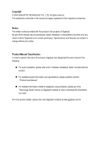
. „ For detailed product information and specifications, please carefully read the "Product User Manual". „ For detailed information related to Gigabyte's unique features, please go to the "Technology Guide" section on Gigabyte's website to read or download the information you need. For more product - Gigabyte GA-8AENXP Dual Graphic | Manual - Page 4
Table of Contents GA-8AENXP Dual Graphic Motherboard Layout 6 Block Diagram ...7 Chapter 1 Hardware Installation 9 1-1 Considerations Prior to 14 1-6 Installation of Expansion Cards 16 1-7 Configuring a Quad View System 17 1-8 Installation of U-Plus DPS (Universal Plus Dual Power System 19 1-9 - Gigabyte GA-8AENXP Dual Graphic | Manual - Page 5
57 4-1-1 EasyTune 5 Introduction 58 4-1-2 Xpress Recovery Introduction 59 4-1-3 Flash BIOS Method Introduction 62 4-1-4 Serial ATA BIOS Setting Utility Introduction 73 4-1-5 2- / 4- / 6- / 8- Channel Audio Function Introduction 85 4-2 Troubleshooting 90 - 5 - - Gigabyte GA-8AENXP Dual Graphic | Manual - Page 6
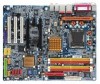
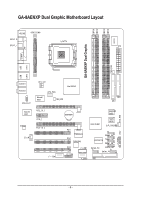
GA-8AENXP Dual Graphic Motherboard Layout DDRII1 DDRII2 DDRII3 DDRII4 IT8712 KB_MS VRM_CONN SPDIF_O LGA775 SPDIF_I ATX GA-8AENXP Dual Graphic COMA LPT PWR_FAN USB LAN1 USB LAN2 SYS_FAN AUDIO1 AUDIO2 AZALIA_FP ATX_12V Marvell 8001 CPU_FAN NB_FAN Intel 925XE FDD IDE1 Marvell 8001 - Gigabyte GA-8AENXP Dual Graphic | Manual - Page 7
/400MHz DIMM Intel 925XE MCH Intel ICH6R Dual Channel Memory MCHCLK (266/200/133MHz) 100MHz 66MHz 33MHz 14.318MHz 48MHz Dual BIOS 4 Serial ATA PDC20779 2 Serial use a DDRII 711 memory module on the motherboard, you must install a 1066MHz FSB processor and overclock in BIOS. To use a DDRII - Gigabyte GA-8AENXP Dual Graphic | Manual - Page 8
- 8 - - Gigabyte GA-8AENXP Dual Graphic | Manual - Page 9
instructions below: 1. Please turn off the computer and unplug its power cord. 2. When handling the motherboard motherboard. Installation Notices 1. Prior to installation, please do not remove the stickers on the motherboard the motherboard or or have a problem related to the the user manual. 3. Damage - Gigabyte GA-8AENXP Dual Graphic | Manual - Page 10
Š Supports the latest Intel® Pentium® 4 LGA775 CPU Š Supports 1066/ motherboard, you must install a 1066MHz FSB processor and overclock in BIOS. To use a DDRII 600 memory module on the motherboard, you must install an 800MHz FSB processor and overclock in BIOS. GA-8AENXP Dual Graphic Motherboard - Gigabyte GA-8AENXP Dual Graphic | Manual - Page 11
on the Win 2000/XP operating systems BIOS Š Use of licensed AWARD BIOS Š Supports Dual BIOS/Q-Flash/Multilanguage BIOS Additional Features Š Supports U-Plus DPS Š Supports @BIOS Š Supports EasyTune 5 Overclocking Š Over Voltage via BIOS (CPU/ DDR II/ PCI-E/ FSB) Š Over Clock via BIOS - Gigabyte GA-8AENXP Dual Graphic | Manual - Page 12
the following conditions: 1. Please make sure that the motherboard supports the CPU. 2. Please take note of the hardware specifications including the CPU, graphics card, memory, hard drive, cause damage to the CPU during installation.) GA-8AENXP Dual Graphic Motherboard - 12 - Fig. 4 Once the - Gigabyte GA-8AENXP Dual Graphic | Manual - Page 13
make sure the Male and Female push pin are joined closely. (for detailed installation instructions, please refer to the heatsink installation section of the user manual) Fig. 5 Please check the back of motherboard after installing. If the push pin is inserted as the picture, the installation is - Gigabyte GA-8AENXP Dual Graphic | Manual - Page 14
. The motherboard supports DDR II memory modules, whereby BIOS will automatically detect memory capacity and specifications. Memory modules are designed so that they can be inserted only in one direction. The memory capacity used can differ with each slot. GA-8AENXP Dual Graphic Motherboard - 14 - Gigabyte GA-8AENXP Dual Graphic | Manual - Page 15
DIMM module. Reverse the installation steps when you wish to remove the DIMM module. Dual Channel DDR II Memory Configuration The GA-8AENXP Dual Graphic supports the Dual Channel Technology. When the Dual Channel Technology is activated, the bandwidth of memory bus will be double the original one - Gigabyte GA-8AENXP Dual Graphic | Manual - Page 16
sure your VGA card is locked by the small white-drawable bar. The GA-8AENXP Dual Graphic will allow a four-monitor configuration(Quad View) when used in conjunction with two PCI Express graphics cards that are based on identical chips and support dual view. GA-8AENXP Dual Graphic Motherboard - 16 - Gigabyte GA-8AENXP Dual Graphic | Manual - Page 17
With Quad View technology from GIGABYTE, Dual Graphic enabled motherboards offer multiple display support on up to four separate install two similar graphics cards into PCIE x 16 slots (it is recommended to use graphics cards of identical brand and chips. For example: GIGABYTE GV-NX66T128D). - Gigabyte GA-8AENXP Dual Graphic | Manual - Page 18
BIOS Setup to PEG; set this item to PEG2 if the card is installed in the PCIE_16_2 slot. Step 2: Graphics Cards Driver Setting For detailed information about how to install the graphics card driver, please refer to the user's manual for your graphics card. GA-8AENXP Dual Graphic Motherboard - 18 - - Gigabyte GA-8AENXP Dual Graphic | Manual - Page 19
Dual Power System) The U-Plus Dual Power System (U-Plus D.P.S.) is a revolutionary eight-phase power circuit built for ultimate system protection. Designed . The U-Plus DPS can work in a Dual Power System: Parallel Mode-U-Plus DPS and motherboard CPU power can work simultaneously, providing a total - Gigabyte GA-8AENXP Dual Graphic | Manual - Page 20
speaker...etc. have a standard USB interface. Also make sure your OS supports USB controller. If your OS does not support USB controller, please contact OS vendor for possible patch or driver upgrade. Connect the Center/Subwoofer speakers to this connector. GA-8AENXP Dual Graphic Motherboard - 20 - - Gigabyte GA-8AENXP Dual Graphic | Manual - Page 21
English Side Speaker Out Connect the side surround speakers to this connector. You can use audio software to configure 2-/4-/6-/8-channel audio functioning. 1-10 Connectors Introduction 13 10 2 5 7 13 8 6 19 17 4 14 18 12 18 17 11 9 1) ATX_12V 11) SATA0_PR /SATA1_PR 2) ATX (Power - Gigabyte GA-8AENXP Dual Graphic | Manual - Page 22
to start. If you use a 24-pin ATX power supply, please remove the small cover on the power connector on the motherboard before plugging in the power cord ; Otherwise, please do not remove it. 42 31 Pin No. 1 2 3 4 -5V 21 +5V 22 +5V 23 +5V 24 GND GA-8AENXP Dual Graphic Motherboard - 22 - - Gigabyte GA-8AENXP Dual Graphic | Manual - Page 23
connector supplies a +12V power voltage via a 3-pin/4-pin(only for CPU_FAN) power connector and possesses a foolproof connection design. Most coolers are designed with color-coded power connector wires. A red power connector wire indicates a positive connection and requires a +12V power voltage - Gigabyte GA-8AENXP Dual Graphic | Manual - Page 24
the other end of the cable connects to the FDD drive. The types of FDD drives supported are: 360KB, 720KB, 1.2MB, 1.44MB and 2.88MB. Please connect the red power connector the instructions located on the IDE device). 40 39 IDE1 2 1 2 40 IDE2 1 39 GA-8AENXP Dual Graphic Motherboard - 24 - - Gigabyte GA-8AENXP Dual Graphic | Manual - Page 25
English 10) SATA0_SB/SATA1_SB/SATA2_SB/SATA3_SB (Serial ATA Connector, Controlled by ICH6R) Serial ATA can provide 150MB/s transfer rate. Please refer to the BIOS setting for the Serial ATA and install the proper driver in order to work properly. Pin No. Definition 1 GND 1 7 2 TXP 3 TXN 4 - Gigabyte GA-8AENXP Dual Graphic | Manual - Page 26
Operation Close: Power On/Off Pin 1: LED anode(+) Pin 2: LED cathode(-) Open: Normal Operation Close: Reset Hardware System Pin 1: LED anode(+) Pin 2: LED cathode(-) NC GA-8AENXP Dual Graphic Motherboard - 26 - - Gigabyte GA-8AENXP Dual Graphic | Manual - Page 27
English 13) AZALIA_FP (Front Audio Panel Connector) This connector is supported to connect HD(High Definition) Audio and AC'97 Audio. Check the pin assignment carefully while you connect the audio panel cable, incorrect connection between - Gigabyte GA-8AENXP Dual Graphic | Manual - Page 28
GND Pin No. 1 2 3 4 5 6 7 8 9 10 11 12 13 14 15 16 Definition Power Power TPA1+ TPA1GND GND TPB1+ TPB1Power Power TPA2+ TPA2GND No Pin TPB2+ TPB2- GA-8AENXP Dual Graphic Motherboard - 28 - - Gigabyte GA-8AENXP Dual Graphic | Manual - Page 29
English 17) CLR_CMOS (Clear CMOS) You may clear the CMOS data to its default values by this jumper. To clear CMOS, temporarily short 1-2 pin. Default doesn't include the "Shunter" to prevent from improper use this jumper. Open: Normal 1 Short: Clear CMOS 1 18) CI (Chassis Intrusion, Case Open) - Gigabyte GA-8AENXP Dual Graphic | Manual - Page 30
batteries according to the manufacturer's instructions. If you want to erase CMOS... 1. Turn OFF the computer and unplug the power cord. 2. Remove the battery, wait for 30 seconds. 3. Re-install the battery. 4. Plug the power cord and turn ON the computer. GA-8AENXP Dual Graphic Motherboard - 30 - - Gigabyte GA-8AENXP Dual Graphic | Manual - Page 31
of the motherboard. When the power is turned off, the battery on the motherboard supplies the you wish to upgrade to a new BIOS, either GIGABYTE's Q-Flash or @BIOS utility can be used. Q-Flash table Load the Optimized Defaults Dual BIOS/Q-Flash utility System Information - Gigabyte GA-8AENXP Dual Graphic | Manual - Page 32
Configurations ` PC Health Status ` MB Intelligent Tweaker(M.I.T.) ESC: Quit F8: Dual BIOS/Q-Flash Select Language Load Fail-Safe Defaults Load Optimized Defaults Set Supervisor Password ratio. „ Select Language This setup page is select multilanguage. GA-8AENXP Dual Graphic Motherboard - 32 - - Gigabyte GA-8AENXP Dual Graphic | Manual - Page 33
English „ Load Fail-Safe Defaults Fail-Safe Defaults indicates the value of the system parameters which the system would be in safe configuration. „ Load Optimized Defaults Optimized Defaults indicates the value of the system parameters which the system would be in best performance configuration. „ - Gigabyte GA-8AENXP Dual Graphic | Manual - Page 34
the system will skip the automatic detection step and allow for faster system start up. • Manual User can manually input the correct settings. Access Mode Use this to set the access mode for the hard has not been installed, select NONE and press . GA-8AENXP Dual Graphic Motherboard - 34 - - Gigabyte GA-8AENXP Dual Graphic | Manual - Page 35
, 3.5" 3.5 inch double-sided drive; 2.88M byte capacity. Floppy 3 Mode Support (for Japan Area) Disabled Normal Floppy Drive. (Default value) Drive A Drive memory installed on the motherboard, or 640K for systems with 640K or more memory installed on the motherboard. Extended Memory The BIOS - Gigabyte GA-8AENXP Dual Graphic | Manual - Page 36
Intel® Pentium® 4 processor with HT Technology. Hard Disk Boot Priority Select boot sequence for onboard(or add-on cards) SCSI, RAID, etc. Use < > or < > to select a device, then press to move when you install a processor which supports this function. GA-8AENXP Dual Graphic Motherboard - 36 - - Gigabyte GA-8AENXP Dual Graphic | Manual - Page 37
for operating system with multi processors mode supported. (Default value) Disabled Disables CPU Hyper card when you install a PCI card and a PCI Express VGA card on the motherboard. In order to enable the Dual Graphic function correctly, you have to connect the display cable to the graphics card - Gigabyte GA-8AENXP Dual Graphic | Manual - Page 38
Default value) Disable onboard 1st channel IDE port. SATA RAID / AHCI Mode RAID Select onboard Serial ATA function as RAID. (Default value) AHCI Support hotplug function under OS. WinXP, 2000 only. Disabled Select onboard Serial ATA function as ATA. GA-8AENXP Dual Graphic Motherboard - 38 - - Gigabyte GA-8AENXP Dual Graphic | Manual - Page 39
motherboard; 2 for SATA and the other for PATA IDE. Set On-Chip SATA mode to Enhanced, the motherboard Support Enabled Enable USB keyboard support. Disabled Disable USB keyboard support. (Default value) USB Mouse Support Enabled Enable USB mouse support. Disabled Disable USB mouse support - Gigabyte GA-8AENXP Dual Graphic | Manual - Page 40
. Using Parallel port as ECP & EPP mode. ECP Mode Use DMA 3 Set ECP Mode Use DMA to 3. (Default value) 1 Set ECP Mode Use DMA to 1. GA-8AENXP Dual Graphic Motherboard - 40 - - Gigabyte GA-8AENXP Dual Graphic | Manual - Page 41
English 2-4 Power Management Setup CMOS Setup Utility-Copyright (C) 1984-2005 Award Software Power Management Setup ACPI Suspend Type Soft-Off by PWR-BTTN PME Event Wake Up Power On by Ring Resume by Alarm x Date (of Month) Alarm x Time (hh:mm:ss) Alarm Power On By Mouse Power On By Keyboard x KB - Gigabyte GA-8AENXP Dual Graphic | Manual - Page 42
system always in "On" state. Memory When AC-power back to the system, the system will return to the Last state before AC-power off. GA-8AENXP Dual Graphic Motherboard - 42 - - Gigabyte GA-8AENXP Dual Graphic | Manual - Page 43
English 2-5 PnP/PCI Configurations CMOS Setup Utility-Copyright (C) 1984-2005 Award Software PnP/PCI Configurations PCI 1 IRQ Assignment PCI 2 IRQ Assignment PCI 3 IRQ Assignment [Auto] [Auto] [Auto] Item Help Menu Level` Device(s) using this INT: KLJI: Move Enter: Select +/-/PU/PD: Value - Gigabyte GA-8AENXP Dual Graphic | Manual - Page 44
/POWER/SYSTEM FAN Fail Warning Disabled Disable CPU/POWER/SYSTEM fan fail warning function. (Default value) Enabled Enable CPU/POWER/SYSTEM fan fail warning function. GA-8AENXP Dual Graphic Motherboard - 44 - - Gigabyte GA-8AENXP Dual Graphic | Manual - Page 45
fact, the Voltage option can be used for CPU fans with 3-pin or 4-pin power cables. However, some 4-pin CPU fan power cables are not designed following Intel 4-wire fans PWM control specifications. With such CPU fans, selecting PWM will not effectively reduce the fan speed. - 45 - BIOS Setup - Gigabyte GA-8AENXP Dual Graphic | Manual - Page 46
: Stability is highly dependent on system components. CPU Host Clock Control Disabled Enabled Disable CPU Host Clock Control. (Default value) Enable CPU Host Clock Control. GA-8AENXP Dual Graphic Motherboard - 46 - - Gigabyte GA-8AENXP Dual Graphic | Manual - Page 47
Increase voltage range as user selected. CPU Voltage Control Supports adjustable CPU Vcore from 0.8375V to 1.6000V. (Default value: Normal) Normal CPU Vcore Display your CPU Vcore voltage. (Note) To use a DDRII 600 memory module on the motherboard, you must install an 800MHz FSB processor and set - Gigabyte GA-8AENXP Dual Graphic | Manual - Page 48
Exit Setup Multi-language supports 7 languages. There are Dual BIOS/Q-Flash F3: Change Language F10: Save & Exit Setup Load Fail-Safe Defaults Fail-Safe defaults contain the most appropriate values of the system parameters that allow minimum system performance. GA-8AENXP Dual Graphic Motherboard - Gigabyte GA-8AENXP Dual Graphic | Manual - Page 49
Exit Setup ` MB Intelligent Tweaker(M.I.T.) Exit Without Saving ESC: Quit F8: Dual BIOS/Q-Flash F3: Change Language F10: Save & Exit Setup Load Optimized User Password Save & Exit Setup Exit Without Saving ESC: Quit F8: Dual BIOS/Q-Flash F3: Change Language F10: Save & Exit Setup Change/Set/ - Gigabyte GA-8AENXP Dual Graphic | Manual - Page 50
PC Health Status Save & Exit Setup ` MB Intelligent Tweaker(M.I.T.) Exit Without Saving ESC: Quit F8: Dual BIOS/Q-Flash F3: Change Language F10: Save & Exit Setup Save & Exit Setup Type "Y" will to RTC CMOS. Type "N" will return to Setup Utility. GA-8AENXP Dual Graphic Motherboard - 50 - - Gigabyte GA-8AENXP Dual Graphic | Manual - Page 51
motherboard into your CD-ROM drive, the driver CD-title will auto start and show the installation guide. If not, please double click the CD-ROM device icon in "My computer", and execute the Run support under Windows XP operating system, please use Windows Service Pack. After install Windows Service - Gigabyte GA-8AENXP Dual Graphic | Manual - Page 52
This page displays all the tools that Gigabyte developed and some free software, you can choose anyone you want and press "install" to install them. 3-3 Driver CD Information This page lists the contents of software and drivers in this CD-title. GA-8AENXP Dual Graphic Motherboard - 52 - - Gigabyte GA-8AENXP Dual Graphic | Manual - Page 53
English 3-4 Hardware Information This page lists all device you have for this motherboard. 3-5 Contact Us Please see the last page for details. - 53 - Drivers Installation - Gigabyte GA-8AENXP Dual Graphic | Manual - Page 54
how to manually install the IEEE 1394 driver. Step 1: After entering operating system, insert the motherboard driver CD Gigabyte 1394b Host Controller (Figure 4). If you see a yellow exclamation or question mark, reinstall the driver for the IEEE 1394 controller. GA-8AENXP Dual Graphic Motherboard - Gigabyte GA-8AENXP Dual Graphic | Manual - Page 55
Microsoft IEEE 1394 driver. To switch from the Unibrain driver to Microsoft driver, you can simply run the Unibrain IEEE 1394 driver switch utility from the motherboard driver CD or manually switch the driver from Device Manager. Method A: Switch IEEE 1394 driver via Unibrain driver switch utility - Gigabyte GA-8AENXP Dual Graphic | Manual - Page 56
IEEE 1394 Bus host controllers, as seen in Figure 9. Step 2: Right-click Gigabyte 1394b Host Controller and select Update Driver (Figure 10). Figure 9 Step 3: When correctly. You may refer to Method A>Step 3. GA-8AENXP Dual Graphic Motherboard - 56 - Figure 10 Figure 11 Figure 12 Figure 13 - Gigabyte GA-8AENXP Dual Graphic | Manual - Page 57
support these Unique Software Utilities, please check your MB features.) U-PLUS D.P.S. (Universal Plus Dual Power System) The U-Plus Dual Power System (U-Plus DPS) is a revolutionary eight-phase power circuit built for ultimate system protection. Designed as CPU, memory, graphics card, etc. to be - Gigabyte GA-8AENXP Dual Graphic | Manual - Page 58
and Advance Mode Display panel of CPU frequency Shows the current functions status Log on to GIGABYTE website Display EasyTuneTM 5 Help file Quit or Minimize EasyTuneTM 5 software (Note) EasyTune 5 functions may vary depending on different motherboards. GA-8AENXP Dual Graphic Motherboard - 58 - - Gigabyte GA-8AENXP Dual Graphic | Manual - Page 59
installation of only one OS 4. Must be used with an IDE hard disk supporting HPA 5. The first partition must be set as the boot partition. When the from CD: Boot from CD: Xpress Recovery V1.0 (C) Copy Right 2003. GIGABYTE Technology CO. , Ltd. 1. Execute Backup Utility 2. Execute Restore Utility - Gigabyte GA-8AENXP Dual Graphic | Manual - Page 60
, An Energy Star Al ly Copyright (C) 1984-2004, Award Software, Inc. Intel 865PE AGPSet BIOS for 8IPE1000MT F1 Check System Health OK . Xpress Recovery Xpress Recovery V1.0 (C) Copy Right 2003. GIGABYTE Technology CO. , Ltd. 1. Execute Backup Utility 2. GA-8AENXP Dual Graphic Motherboard - 60 - - Gigabyte GA-8AENXP Dual Graphic | Manual - Page 61
Esc to Exit The backup utility will automatically scan your system and back up data as a backup image in your hard drive. Not all systems support access to Xpress Recovery by pressing the F9 key during computer power on. If this is the case, please use the boot from CD-ROM - Gigabyte GA-8AENXP Dual Graphic | Manual - Page 62
is powered on. This means that your PC will still be able to run stably as if nothing has happened in your BIOS. B. How to use Dual BIOS and Q-Flash Utility? a. After power on the computer, pressing < : Modify : Move ESC: Reset 512K 512K F10: Power Off GA-8AENXP Dual Graphic Motherboard - 62 - - Gigabyte GA-8AENXP Dual Graphic | Manual - Page 63
. Status 2: If the ROM BIOS on peripherals cards(ex. SCSI Cards, LAN Cards,..) emits signals to request restart of the system , and the system will pause and wait for the user's instruction. If Auto Recovery :Disable, it will show - Gigabyte GA-8AENXP Dual Graphic | Manual - Page 64
Dual BIOS Motherboards. Some of Gigabyte motherboards are equipped with dual BIOS. In the BIOS menu of the motherboards supporting Q-Flash and Dual BIOS, the Q-Flash utility and Dual / Dual BIOS / Q-Flash / F9 For Xpress Recovery 08/07/2003-i875P-6A79BG03C-00 GA-8AENXP Dual Graphic Motherboard - 64 - Gigabyte GA-8AENXP Dual Graphic | Manual - Page 65
Backup BIOS from Floppy Save Main BIOS to Floppy Save Backup BIOS to Floppy Enter : Run :Move ESC:Reset F10:Power Off Dual BIOS utility bar Q-FlashTM utility title bar Action bar Task menu for Dual BIOS utility: Contains the names of eight tasks and two item showing information about the BIOS - Gigabyte GA-8AENXP Dual Graphic | Manual - Page 66
BIOS to Floppy Save Backup BIOS to Floppy Enter : Run :Move ESC:Reset F10:Power Off Do not turn off power or reset your system at this stage!! After BIOS file is read, you'll see a confirmation dialog box asking you "Are you sure to update BIOS?" GA-8AENXP Dual Graphic Motherboard - 66 - - Gigabyte GA-8AENXP Dual Graphic | Manual - Page 67
when the BIOS updating procedure is completed. Dual BIOS Utility Boot From Main Bios Main ROM Floppy Save Backup BIOS to Floppy Enter : Run :Move ESC:Reset F10:Power Off After system Energy Star Ally Copyright (C) 1984-2003, Award Software, Inc. Intel i875P AGPset BIOS for 8KNXP Ultra Fba Check - Gigabyte GA-8AENXP Dual Graphic | Manual - Page 68
Defaults Set Supervisor Password Set User Password Save & Exit Setup Exit Without Saving F3: Change Language F10: Save & Exit Setup Time, Date, Hard Disk Type... GA-8AENXP Dual Graphic Motherboard - 68 - - Gigabyte GA-8AENXP Dual Graphic | Manual - Page 69
256K Q-FlashTM utility bar Task menu for Q-FlashTM utility Enter : Run Keep DMI Data Enable Update BIOS from Floppy Save BIOS to Floppy section above, you must prepare a floppy disk having the BIOS file for your motherboard and insert it to your computer. If you have already put the floppy - Gigabyte GA-8AENXP Dual Graphic | Manual - Page 70
AUrepdyaotue BsuIrOeStofroRmESFEloTpp?y Save BIOS to Floppy Enter : Run[Enter] to:Mcoonvteinure oErS[CE:sRce]steot abort..F. , An Energy Star Ally Copyright (C) 1984-2003, Award Software, Inc. Intel 845GE AGPSet BIOS for 8GE800 F4 Check System Health OK GA-8AENXP Dual Graphic Motherboard - 70 - - Gigabyte GA-8AENXP Dual Graphic | Manual - Page 71
@BIOS utility Fig 2. Installation complete and run @BIOS Click Sart/ Programs/ GIGABYTE/@BIOS Select @BIOS item than click Install Fig @BIOSTM sever d. Select the exact model name on your motherboard e. System will automatically download and update the BIOS. II. instruction. - 71 - Appendix - Gigabyte GA-8AENXP Dual Graphic | Manual - Page 72
the current BIOS version. IV. Check out supported motherboard and Flash ROM: In the very beginning, there Gigabyte's web site for downloading and updating it according to method II. IV. Please note that any interruption during updating will cause system unbooted GA-8AENXP Dual Graphic Motherboard - Gigabyte GA-8AENXP Dual Graphic | Manual - Page 73
number of drive members times the capacity of the smallest member. The striping block size can be set from 4KB to 128KB. RAID 0 does not support fault tolerance. RAID 1 (Mirroring) RAID 1 writes duplicate data onto a pair of drives and reads both sets of data in parallel. If one of the mirrored - Gigabyte GA-8AENXP Dual Graphic | Manual - Page 74
For more detailed setup information, please visit "Support\ Motherboard\ Technology Guide section" on our website at http:\\www.gigabyte.com.tw to read or download the information -RAID Disk 111.7GB Non-RAID Disk [ ]-Select GA-8AENXP Dual Graphic Motherboard [ESC]-Exit - 74 - [ENTER]-Select Menu - Gigabyte GA-8AENXP Dual Graphic | Manual - Page 75
English Create RAID Volume Press Enter under Create RAID Volume to set up RAID. Intel(R) Application Accelerator RAID Option ROM v4.0.6180 Copyright(C) 2003-04 Intel Corporation. All Rights Reversed. [ CREATE VOLUME MENU ] Name : RAID Level : Disks : Strip Size : Capacity : RAID_Volume0 RAID0( - Gigabyte GA-8AENXP Dual Graphic | Manual - Page 76
is needed to utilize the remaining space. [ ]-Change [TAB]-Next [ESC]-Previous Menu Press Enter to enter Create Volume after setting disk capacity. [ENTER]-Select GA-8AENXP Dual Graphic Motherboard - 76 - - Gigabyte GA-8AENXP Dual Graphic | Manual - Page 77
English Press Enter under the Create Volume item. Intel(R) Application Accelerator RAID Option ROM v4.0.6180 Copyright(C) 2003-04 Intel Corporation. All Rights Reversed. [ CREATE VOLUME MENU ] Name : RAID Level : Disks : Strip Size : Capacity : RAID_Volume0 RAID0(Stripe) Select Disks 128KB 223 - Gigabyte GA-8AENXP Dual Graphic | Manual - Page 78
volume, please select the Delete RAID Volume option. Press Enter key and follow the instructions on the screen. Intel(R) Application Accelerator RAID Option ROM v4.0.6180 Copyright(C) 2003-04 7GB Member Disk(0) [ ]-Select [ESC]-Exit [ENTER]-Select Menu GA-8AENXP Dual Graphic Motherboard - 78 - - Gigabyte GA-8AENXP Dual Graphic | Manual - Page 79
FastTrak 779 (tm) BIOS Version 2.00.0.24 Copyright (c) 2003 Promise Technology, Inc. Updated in 2004 No Array is defined Press to enter FastBuild ( , press . Promise recommends this option for most users. To manually create an array, press to enter the Define Array window. - Gigabyte GA-8AENXP Dual Graphic | Manual - Page 80
for the disk array you are creating. FastBuild (tm) 2.03 (c) 2003-2005 Promise Technology, Inc. Optimize Array for: [ Auto Setup Options Menu ] ] Performance [ Array Setup Configuration ] RAID 1), FastTrak assigns two drives to a single Mirrored array. GA-8AENXP Dual Graphic Motherboard - 80 - - Gigabyte GA-8AENXP Dual Graphic | Manual - Page 81
selection from the Main Menu allows users to begin the process of manually defining the drive elements and RAID levels for one or multiple , Inc. Logical Disk No [ Define Array Menu ] RAID Mode Total Drv Status Logical Disk 1 Stripe 0 Functional Stripe Block: 64KB Gigabyte Rounding - Gigabyte GA-8AENXP Dual Graphic | Manual - Page 82
manually select the stripe block size. Press the Space bar to scroll through choices from 32 to 128KB. The default is 64KB. Gigabyte Rounding: The Gigabyte Rounding feature is designed (c) 2003-2005 Promise Technology, Inc. [ View/Change Drives Assignments GA-8AENXP Dual Graphic Motherboard - 82 - - Gigabyte GA-8AENXP Dual Graphic | Manual - Page 83
to undo a deletion. FastBuild (tm) 2.03 (c) 2003-2005 Promise Technology, Inc. Logical Disk No [ Delete Array Menu ] ] RAID Mode Total Drv Capacity Status Logical Disk 1 Stripe 2 240068 Functional Stripe Block: 64KB Gigabyte Rounding: OFF Channel:ID 1:SATA 2:SATA [ Drives Assignments ] - Gigabyte GA-8AENXP Dual Graphic | Manual - Page 84
or XP boots up, then supply serial ATA controller driver by this floppy disk. Follow on-screen instructions to complete installation. (Each time you add a new hard drive to a RAID array, the list, Intel Application Accelerator 4.0 is Intel ICH6R chipset. GA-8AENXP Dual Graphic Motherboard - 84 - - Gigabyte GA-8AENXP Dual Graphic | Manual - Page 85
Panel Type option to HD Audio in BIOS, make sure to connect your audio front panel cable(optional for different models) connector to the motherboard before system startup or you'll not be able to see the front panel options from the Sound Effect application. Stereo Speakers Connection and Settings - Gigabyte GA-8AENXP Dual Graphic | Manual - Page 86
icon to select the function. STEP 3: Click "Speaker Configuration" then click on the left selection bar and select "4CH Speaker" to complete 4 channel audio configuration. GA-8AENXP Dual Graphic Motherboard - 86 - Front Speaker Out Rear Speaker Out - Gigabyte GA-8AENXP Dual Graphic | Manual - Page 87
English 6 Channel Audio Setup STEP 1 : Connect the front channels to "Front Speaker Out", the rear channels to "Rear Speaker Out", and the Center/Subwoofer channels to "Center/Subwoofer Speaker Out". STEP 2 : Following installation of the audio driver, you'll find a Sound Effect icon on the lower - Gigabyte GA-8AENXP Dual Graphic | Manual - Page 88
the sound effect menu, users can adjust sound option settings as desired. Front Speaker Out Rear Speaker Out Center/Subwoofer Speaker Out Side Speaker Out GA-8AENXP Dual Graphic Motherboard - 88 - - Gigabyte GA-8AENXP Dual Graphic | Manual - Page 89
function. Install Microsoft DirectX8.1 or later version before to enable Jack-Sensing support for Windows 2000. After you install an audio device, a screen of to the correct jack following the arrow instruction. The correct icon for audio device will be displayed after the reinstallation. - - Gigabyte GA-8AENXP Dual Graphic | Manual - Page 90
user manual and check whether you have connected any cable that is not provided with the motherboard package to the USB Over Current pin in the Front USB Panel. If the cable is your own cable, please remove it from this pin and do not connect any of your own cables to it. GA-8AENXP Dual Graphic - Gigabyte GA-8AENXP Dual Graphic | Manual - Page 91
Answer: The beep codes below may help you identify the possible computer problems. However, they are only for reference purposes. The situations might differ long 1 short: DRAM or M/B error 1 long 2 short: Monitor or display card error 1 long 3 short: Keyboard error 1 long 9 short: BIOS ROM error - Gigabyte GA-8AENXP Dual Graphic | Manual - Page 92
English GA-8AENXP Dual Graphic Motherboard - 92 - - Gigabyte GA-8AENXP Dual Graphic | Manual - Page 93
- 93 - Appendix English - Gigabyte GA-8AENXP Dual Graphic | Manual - Page 94
English GA-8AENXP Dual Graphic Motherboard - 94 - - Gigabyte GA-8AENXP Dual Graphic | Manual - Page 95
tw.giga-byte.com/TechSupport/ServiceCenter.htm Non-Tech. Support(Sales/Marketing) : http://ggts.gigabyte.com.tw/nontech.asp WEB address (English): http://www.gigabyte.com.tw WEB address (Chinese): http://chinese.giga-byte.com U.S.A. G.B.T. INC. Address: 17358 Railroad St, City of Industry, CA 91748 - Gigabyte GA-8AENXP Dual Graphic | Manual - Page 96
ru Poland Representative Office Of Giga-Byte Technology Co., Ltd. POLAND Tech. Support : http://tw.giga-byte.com/TechSupport/ServiceCenter.htm Non-Tech. Support(Sales/Marketing) : http://ggts.gigabyte.com.tw/nontech.asp WEB address : http://www.gigabyte.pl GA-8AENXP Dual Graphic Motherboard - 96 -
-
 1
1 -
 2
2 -
 3
3 -
 4
4 -
 5
5 -
 6
6 -
 7
7 -
8
-
9
-
10
-
11
-
12
-
13
-
14
-
15
-
16
-
17
-
18
-
19
-
20
-
21
-
22
-
23
-
24
-
25
-
26
-
27
-
28
-
29
-
30
-
31
-
32
-
33
-
34
-
35
-
36
-
37
-
38
-
39
-
40
-
41
-
42
-
43
-
44
-
45
-
46
-
47
-
48
-
49
-
50
-
51
-
52
-
53
-
54
-
55
-
56
-
57
-
58
-
59
-
60
-
61
-
62
-
63
-
64
-
65
-
66
-
67
-
68
-
69
-
70
-
71
-
72
-
73
-
74
-
75
-
76
-
77
-
78
-
79
-
80
-
81
-
82
-
83
-
84
-
85
-
86
-
87
-
88
-
89
-
90
-
91
-
92
-
93
-
94
-
95
-
96
 |
 |

GA-8AENXP Dual Graphic
Intel
®
Pentium
®
4 LGA775 Processor Motherboard
User's Manual
Rev. 1001
12ME-8AENXPDG-1001