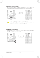
Gigabyte GA-Q67M-D2H-B3 Manual - Page 21
LPT Parallel Port Header, DEBUG PORT Debug Card Header
 |
UPC - 818313012685
View all Gigabyte GA-Q67M-D2H-B3 manuals
Add to My Manuals
Save this manual to your list of manuals |
Page 21 highlights
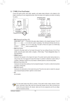
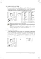
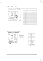
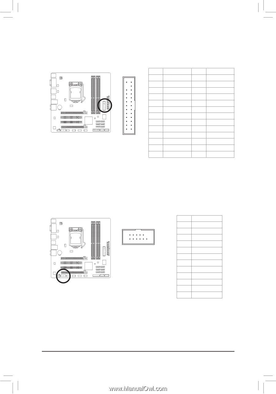
13) LPT (Parallel Port Header) The LPT header can provide one parallel port via an optional LPT port cable. For purchasing the optional LPT port cable, please contact the local dealer. Pin No. Definition Pin No. Definition 26 25 1 STB- 14 GND 2 AFD- 15 PD6 3 PD0 16 GND 4 ERR- 17 PD7 5 PD1 18 GND 6 INIT- 19 ACK- 7 PD2 20 GND 8 SLIN- 21 BUSY 2 1 9 PD3 10 GND 22 GND 23 PE 11 PD4 24 No Pin 12 GND 25 SLCT 13 PD5 26 GND 14) DEBUG PORT (Debug Card Header) The header can connect one debug card. 11 1 12 2 Pin No. 1 2 3 4 5 6 7 8 9 10 11 12 Definition No Pin GND VCC3 LAD0 LAD1 LAD2 LAD3 -LFRAME -PFMRST DB CLK DB_P_SENSOR NC - 21 - Hardware Installation
-
 1
1 -
2
-
3
-
4
-
5
-
6
-
7
-
8
-
9
-
10
-
11
-
12
-
13
-
14
-
15
-
 16
16 -
 17
17 -
 18
18 -
 19
19 -
 20
20 -
 21
21 -
 22
22 -
 23
23 -
 24
24 -
 25
25 -
 26
26 -
27
-
28
-
29
-
30
-
31
-
32
 |
 |
- 21 -
Hardware Installation
13) LPT (Parallel Port Header)
The LPT header can provide one parallel port via an optional LPT port cable. For purchasing the optional
LPT port cable, please contact the local dealer.
Pin No.
Definition
Pin No.
Definition
1
STB-
14
GND
2
AFD-
15
PD6
3
PD0
16
GND
4
ERR-
17
PD7
5
PD1
18
GND
6
INIT-
19
ACK-
7
PD2
20
GND
8
SLIN-
21
BUSY
9
PD3
22
GND
10
GND
23
PE
11
PD4
24
No Pin
12
GND
25
SLCT
13
PD5
26
GND
26
25
2
1
14) DEBUG PORT (Debug Card Header)
The header can connect one debug card.
Pin No.
Definition
1
No Pin
2
GND
3
VCC3
4
LAD0
5
LAD1
6
LAD2
7
LAD3
8
-LFRAME
9
-PFMRST
10
DB CLK
11
DB_P_SENSOR
12
NC
12
11
2
1