Gigabyte M5NM1AI User Manual - Page 14
Internal Connectors
 |
View all Gigabyte M5NM1AI manuals
Add to My Manuals
Save this manual to your list of manuals |
Page 14 highlights
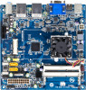
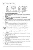
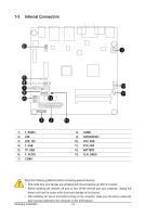
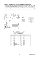
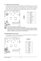
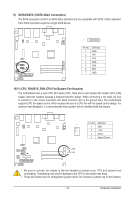
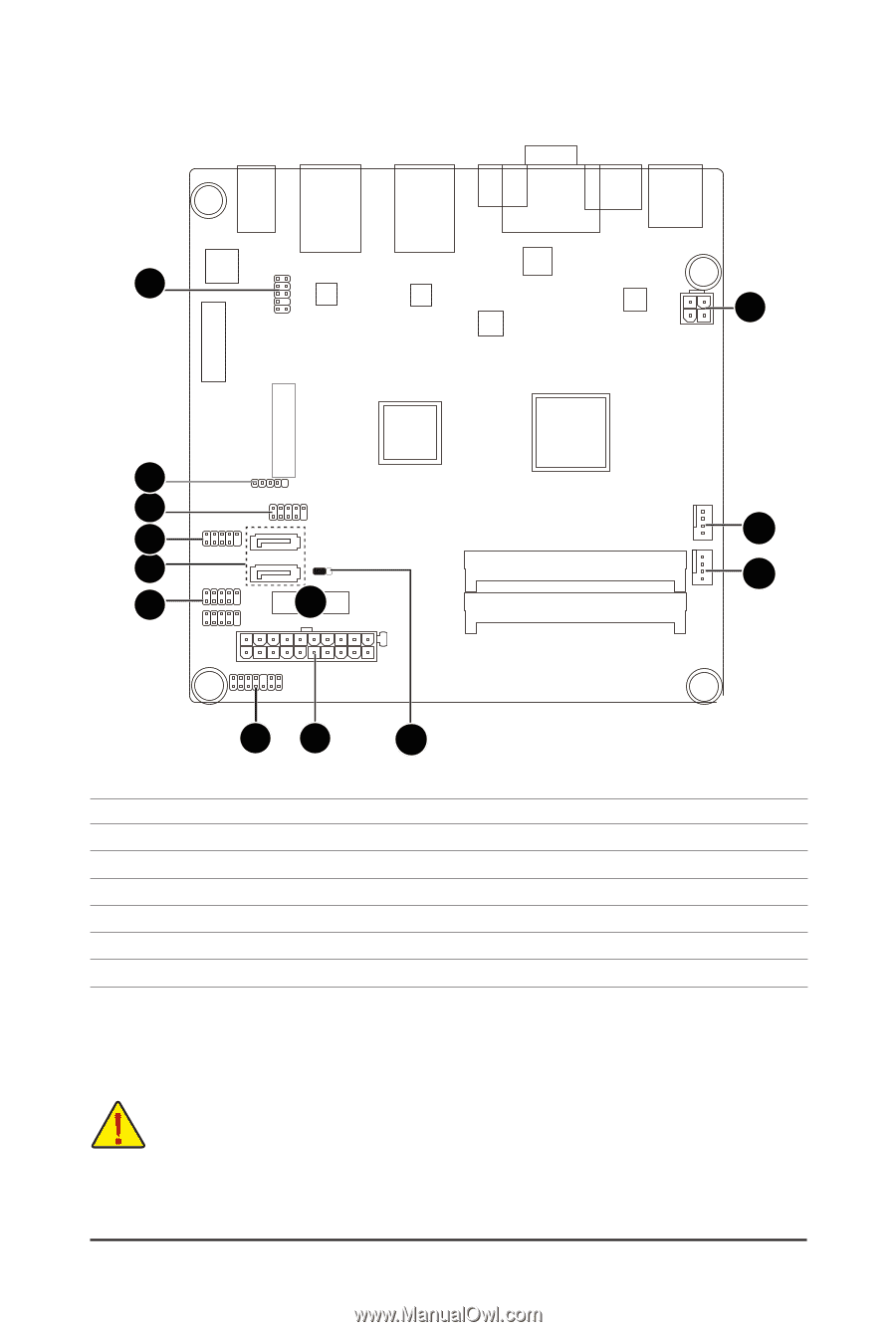
1-5 Internal Connectors 6 3 5 4 7 10 9 11 8 12 12 1) F_PANEL 2) ATX 3) ATX_12V 4) F_USB 5) TP_USB 6) F_AUDIO 7) COMA 13 8) COMB 9) SATA0/SATA1 10) CPU_FAN 11) SYS_FAN 12) BATTERY 13) CLR_CMOS Read the following guidelines before connecting external devices: • First make sure your devices are compliant with the connectors you wish to connect. • Before installing the devices, be sure to turn off the devices and your computer. Unplug the power cord from the power outlet to prevent damage to the devices. • After installing the device and before turning on the computer, make sure the device cable has been securely attached to the connector on the motherboard. Hardware Installation - 14 -
-
 1
1 -
2
-
3
-
4
-
5
-
6
-
7
-
8
-
 9
9 -
 10
10 -
 11
11 -
 12
12 -
 13
13 -
 14
14 -
 15
15 -
 16
16 -
 17
17 -
 18
18 -
 19
19 -
20
-
21
-
22
-
23
-
24
-
25
-
26
-
27
-
28
-
29
-
30
-
31
-
32
-
33
-
34
-
35
-
36
-
37
 |
 |
Hardware Installation
- 14 -
1-5
Internal Connectors
Read the following guidelines before connecting external devices:
•
First make sure your devices are compliant with the connectors you wish to connect.
•
Before installing the devices, be sure to turn off the devices and your computer. Unplug the
power cord from the power outlet to prevent damage to the devices.
•
After installing the device and before turning on the computer, make sure the device cable has
been securely attached to the connector on the motherboard.
1)
F_PANEL
2)
ATX
3)
ATX_12V
4)
F_USB
5)
TP_USB
6)
F_AUDIO
7)
COMA
8)
COMB
9)
SATA0/SATA1
10)
CPU_FAN
11)
SYS_FAN
12)
BATTERY
13)
CLR_CMOS
1
2
3
4
6
9
8
7
5
10
11
12
13