Gigabyte M5NM1AI User Manual - Page 16
ATX/ATX_12V 2x2 12V Power Connector and 2x10 Main Power Connector
 |
View all Gigabyte M5NM1AI manuals
Add to My Manuals
Save this manual to your list of manuals |
Page 16 highlights
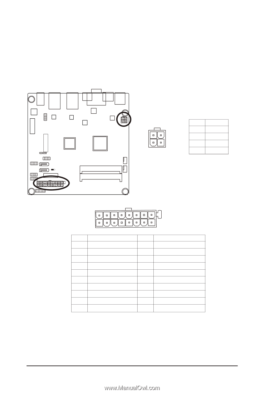
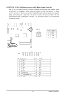
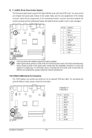
2/3) ATX/ATX_12V (2x2 12V Power Connector and 2x10 Main Power Connector) With the use of the power connector, the power supply can supply enough stable power to all the components on the motherboard. Before connecting the power connector, first make sure the power supply is turned off and all devices are properly installed. The power connector possesses a foolproof design. Connect the power supply cable to the power connector in the correct orientation. The 12V power connector mainly supplies power to the CPU. If the 12V power connector is not connected, the computer will not start. ATX_12V FDD ATX_12V 3 4 1 2 Pin No. 1 2 3 4 Definition GND GND +12V +12V 20 ATX 10 11 1 Pin No. Definition 1 3.3V 2 3.3V 3 GND 4 +5V 5 GND 6 +5V 7 IDEGND 8 Power Good 9 5VSB (stand by +5V) 10 +12V Pin No. 11 12 13 14 15 16 17 18 19 20 Definition +12V 3.3V 3.3V -12V GND PS_ON GND GND GND -5V - 16 - Hardware Installation
-
 1
1 -
2
-
3
-
4
-
5
-
6
-
7
-
8
-
9
-
10
-
 11
11 -
 12
12 -
 13
13 -
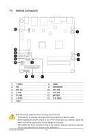 14
14 -
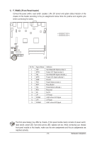 15
15 -
 16
16 -
 17
17 -
 18
18 -
 19
19 -
 20
20 -
 21
21 -
22
-
23
-
24
-
25
-
26
-
27
-
28
-
29
-
30
-
31
-
32
-
33
-
34
-
35
-
36
-
37
 |
 |