Harman Kardon DPR 1001 Owners Manual - Page 6
panel: i.e., Test Tone, Speaker, Channel, Digital Select - dpr remote
 |
View all Harman Kardon DPR 1001 manuals
Add to My Manuals
Save this manual to your list of manuals |
Page 6 highlights
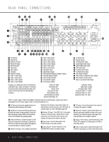
FRONT PANEL CONTROLS This button is also used to switch between Stereo and Mono modes for FM radio reception. When weak reception is encountered, press the button to switch to the Mono mode. Press it again to switch back to Stereo mode. (See page 28 for more information on using the tuner.) 7 Tuning Selector: Press the left side of the button to tune lower-frequency stations and the right side of the button to tune higher-frequency stations. In Manual tuning mode, tap the button lightly and the tuner will step up one frequency increment per button press. When the button is held for a few seconds, the unit will quickly advance through the frequency band. Release it and the tuner will stop. In Auto tuning mode, each press of the button will search for the next station with an acceptable signal. Press and hold the button to skip through the acceptable stations. When the button is released, the tuner will not stop until it reaches a station with an acceptable signal. To switch back and forth between the Auto and Manual tuning modes, press the Tuning Mode Selector 6. 8 Preset Station Selector: Press this button to scroll up or down through the list or stations that have been entered into the preset memory. (See page 28 for more information on tuner programming.) 9 ¤ Button: Use this button to scroll through the System Configuration modes indicated on the front panel: i.e., Test Tone, Speaker, Channel, Digital Select and Delay. Press the Set Button ! to select a configuration mode, and use this button or the ⁄ Button B to scroll through the available adjustments for each System Configuration mode. (See pages 17-23 for more information on configuring the DPR 1001.) ! Set Button: Press this button to access the configuration menus for Test Tone, Speakers Channel Trim, Digital Input Select or Delay. After pressing the button, use the ⁄/¤ Buttons 9B to select the desired menu. (See pages 17-23 for more information.) B ⁄ Button: Use this button to scroll through the System Configuration modes indicated on the front panel: i.e., Test Tone, Speaker, Channel, Digital Select and Delay. Press the Set Button ! to select a configuration mode, and use this button or the ¤ Button 9 to scroll through the available adjustments for each System Configuration mode. (See pages 17-23 for more information on configuring the DPR 1001.) C Door: Gently pull the upper right corner of this door, indicated by the word "Open", toward you to reveal additional front panel jacks and controls. D Volume Control: Turn this knob clockwise to increase the volume, counterclockwise to decrease the volume. If the DPR 1001 is muted, adjusting the volume control will automatically release the unit from the silenced condition. E System Configuration Indicators: One of these indicators will light, after the Set Button ! has been pressed, to indicate which configuration option is in use. Press the ⁄/¤ Buttons 9B to change the selection. (See pages 17-23 for more information.) F Main Information Display: This display delivers messages and status indications to help you operate the receiver. (See page 7 for a complete explanation of the Main Information Display.) G Input Indicators: An LED will light to the left of the input that is currently the input source for the DPR 1001. H Surround Mode Indicators: An LED will light in front of the surround mode that is currently in use. I Main Power Switch: Press this button in to apply power to the DPR 1001. When the switch is pressed in, the unit is placed in a Standby mode, as indicated by the red Power Indicator 0. This button must be pressed in to operate the unit. To turn the unit off and prevent the use of the remote control, this switch should be pressed until it pops out from the front panel. NOTE: This switch is normally left in the "ON" position. J Headphone Jack: This jack may be used to listen to the DPR 1001's output through a pair of headphones. Be certain that the headphones have a standard 1/4" stereo phone plug. The main room speakers will automatically be turned off when the headphone jack is in use. K Digital Optical 3 Input: Connect the optical digital audio output of an audio or video product to this jack. When the input is not in use, be certain to keep the plastic cap installed to avoid dust contamination that might degrade future performance. L Input/Output Status Indicators: These LED indicators will normally light green to show that the front panel Digital Coax 3 Jack M or Video 4 Input/ Output Jacks N are operating as inputs. When either of these jacks has been configured for use as an output, the indicator will turn red to show that the jack may be used for recording. (See page 18 or 29 for more information on configuring the front panel jacks as outputs, rather than inputs.) M Digital Coax 3 Jack: This jack is normally used for connection to the output of portable audio devices, video game consoles or other products that have a coax digital audio jack. It may also be configured as an output jack, to feed a digital signal to a CD-R, MiniDisc or other digital recording device. (See page 18 or 29 for information on configuring the Digital Coax 3 Jack as an output.) N Video 4 Input/Output Jacks: These audio/video jacks may be used for temporary connection to video games or portable audio/video products such as camcorders and portable audio players. These jacks may also be configured as an output to feed an analog audio/video signal to a VCR, camcorder, tape deck or other recording device. (See page 18 or 29 for information on configuring the Video 4 jacks as outputs.) 6 FRONT PANEL CONTROLS
-
 1
1 -
 2
2 -
 3
3 -
 4
4 -
 5
5 -
 6
6 -
 7
7 -
 8
8 -
 9
9 -
 10
10 -
 11
11 -
 12
12 -
13
-
14
-
15
-
16
-
17
-
18
-
19
-
20
-
21
-
22
-
23
-
24
-
25
-
26
-
27
-
28
-
29
-
30
-
31
-
32
-
33
-
34
-
35
-
36
-
37
-
38
-
39
-
40
-
41
-
42
-
43
-
44
 |
 |
