Hayward AquaRite w/TurboCell for Pools up to 25 000 Gallons AquaRite-Electroni - Page 13
Plumbing, Wiring
 |
View all Hayward AquaRite w/TurboCell for Pools up to 25 000 Gallons manuals
Add to My Manuals
Save this manual to your list of manuals |
Page 13 highlights
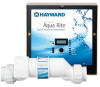
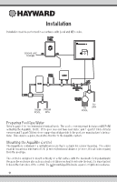
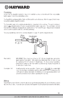
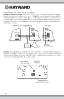
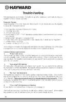
Plumbing Ensure that the AquaRite installation does not constitute a cross connection with the local potable water supply. Consult local plumbing codes. The AquaRite is packaged with a Turbo cell, flow switch and cell unions. Refer to page 2 for information about available AquaRite models. The flow switch and cell should be plumbed in the return line to the pool/spa. The preferred installation is after (downstream) all the pool equipment (filter, heater, solar, etc.). The electrolytic cell and flow switch tee fitting are designed to be plumbed into 2" (51mm) PVC pipe. Adapters (not included) can be used for systems with 1½" (38 mm) plumbing. For proper plumbing, refer to the overview diagram on page 11 and the diagram below. Flow Switch Electrolytic Cell 12" min 3 Way Valve POOL SPA Flow Switch: Electrolytic Cell: IMPORTANT: There must be at least a 12" (25cm) straight pipe run before (upstream) the flow switch. If the switch is plumbed after the cell, the cell can by counted as the 12" (25cm) of straight pipe. To ensure proper operation, verify that the arrow on the flow switch (located on top of gray hex) points in the direction of water flow. Install using the unions provided. Tighten unions BY HAND for a watertight seal. For pool/spa combination systems with spillover, use configurations #2 or #3 above to allow chlorination of both the pool and spa during spillover but preventing overchlorination when operating the spa only. Wiring Power must be shut off at the circuit breaker before performing any wiring. Be sure to follow Local and NEC electrical codes. To provide safe operation, the AquaRite must be properly grounded and bonded. 12 USE ONLY HAYWARD GENUINE REPLACEMENT PARTS
-
 1
1 -
2
-
3
-
4
-
5
-
6
-
7
-
 8
8 -
 9
9 -
 10
10 -
 11
11 -
 12
12 -
 13
13 -
 14
14 -
 15
15 -
 16
16 -
 17
17 -
 18
18 -
19
-
20
-
21
-
22
-
23
-
24
-
25
-
26
-
27
-
28
-
29
-
30
-
31
-
32
-
33
-
34
-
35
-
36
-
37
-
38
-
39
-
40
 |
 |