Hayward AquaRite w/TurboCell for Pools up to 25 000 Gallons AquaRite-Electroni - Page 16
Troubleshooting
 |
View all Hayward AquaRite w/TurboCell for Pools up to 25 000 Gallons manuals
Add to My Manuals
Save this manual to your list of manuals |
Page 16 highlights
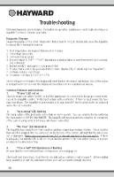
Troubleshooting Visit www.hayward.com for helpful information on operation, maintenance and troubleshooting your AquaRite Electronic Chlorine Generator. Diagnostic Displays Sequential pushes of the small "diagnostic" button next to the LCD display will cause the AquaRite to display the following information: 1. Pool temperature (xx degrees Fahrenheit or Celsius) 2. Cell voltage (xx.x volts) 3. Cell current (x.xx amps) 4. Desired Output % ("0P" -- "100P" depending on knob position or input from remote pool automa- tion controller) 5. Instant salinity ( -xxxx ppm or -x.xx grams/Liter) 6. Product name sent to the pool automation control display ("AL-0" which signifies "AquaRite") 7. Software revision level (r1.xx) 8. Chlorinator cell type (t-3, t-5, t-9, t-15) On the 9th push of the button the display will revert back to the default salt display. Also, if the button is not pushed for 30 seconds, the display will revert back to the standard salt display. Common Problems and Solutions 1. "Power" LED not on Check to make sure either 120VAC or 240VAC input power is connected to the proper screw termi- nals at the AquaRite control. Verify input voltage with a voltmeter. If there is input power, the fuse may have blown. The AquaRite is protected by a 20 amp mini ATO fuse located on the circuit board above the cell connector. 2. "Generating" LED flashing The temperature of the pool water is too high or low to operate. You can override this by switching the main switch to SUPER CHLORINATE. The AquaRite will run at maximum output for the remainder of the current pump cycle or 24 hours, whichever comes first. 3. "No Flow" LED illuminated The AquaRite has sensed a no flow condition and has stopped generating chlorine. Check that the flow switch is plugged into the connector on the bottom of the control unit and that the wire is not cut or damaged. Make sure you have at least 12" of straight pipe before the flow switch. If there is adequate flow and the LED is still on, check that the arrows on the flow switch (on top of hex) are pointing in the direction of flow. 4. "Check Salt" LED illuminated or flashing Be sure that the correct model Turbo Cell has been selected (page 8). Check salt level in pool/spa. If salt level is low, add salt according to chart on page 5. Before adding large quantities of salt, it is advisable to have your salt level professionally checked. 15 USE ONLY HAYWARD GENUINE REPLACEMENT PARTS
-
 1
1 -
2
-
3
-
4
-
5
-
6
-
7
-
8
-
9
-
10
-
 11
11 -
 12
12 -
 13
13 -
 14
14 -
 15
15 -
 16
16 -
 17
17 -
 18
18 -
 19
19 -
 20
20 -
 21
21 -
22
-
23
-
24
-
25
-
26
-
27
-
28
-
29
-
30
-
31
-
32
-
33
-
34
-
35
-
36
-
37
-
38
-
39
-
40
 |
 |